smps3k

Acca

New member
Hello all :)
I try to make simple but powerfull SMPS for audio amp. or similar equipment.
I have one IGBT brick SKM75GB123,and I like to use it in SMPS.
This IGBT isn't for high frequencies,and this means that oscillator must have f. about 20~30kHz.
I make a simple oscillator like from CFL bulb or similar device but with voltage feedback.
Oscilator make fine square waves with +/-16V amplitude.This is fine for IGBT.
In IGBT gate I add 56R and diode,diode is for fast turn off and 56R is used to make small delay on turn on.This will prevent cross conduction.56R may wary if use another type of IGBT.Fet's can be used too.For small FET's and IGBT's like IRFP460 and IRG4PC40W use about 100R instead of 56.
It's tested about half hour on 1kW continiously,IGBT is warm,oscillator is cool
In few days I'll try to make pcb.Tomorrow I'll post some pictures in operating.
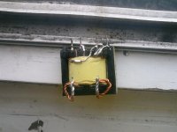
BDT core is salvaged from CFL bulb.This is small toroid :)
E33 can be used original,without rewinding.I'll explain tomorrow how to do it.
Now,here's schematic:
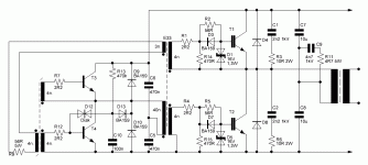
smps3k.GIF
Input rectifier and filter is ommited for simplicity.Secondary rectifier have storage inductor after diodes.
 
Last edited:

Acca

New member
Tests in progress.It work ok,but I like to do more tests :)
t3 and t4 any sw. transistor,I salvaged it from atx,tested with 13007 and BUL56D.
 
Last edited:

Acca

New member
Tests

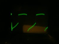
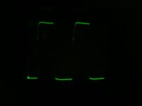
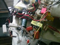
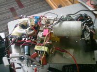
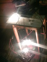
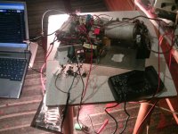
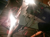
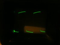
Here's pictures from some tests.Tomorrow I'll try to power 2kW heater.
PTDC0011.JPGPTDC0015.JPGPTDC0018.JPGPTDC0024.JPGPTDC0025.JPGPTDC0026.JPGPTDC0027.JPGPTDC0030.JPGPTDC0001.JPG
Oscillograms is for BJT base,for IGBT gate and for output.
 
Last edited:

MicrosiM

Administrator
Staff member
I really like the setup, also good waves you have, But I think you need to adjust the DT


Regards
 

Acca

New member
Hi Microsim,
DT is ok.It's not seen without load but when I load it,DT is seen.I'll show you when recharge batteries on camera :)
This version maybe will be used,but not tested yet.Test will be in few days.
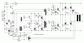
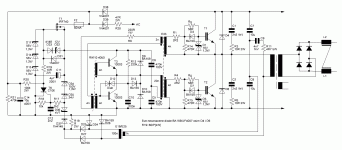
smps3k reg.gif
 

stewin

Member
wow acca. very excellent work does it sense over load and shuts down it self? and with igbt irg4pc50u and er42 core can it produce 2.5kwts? what are the vaues of t5 and the cores ? aso what is the switching frequency?
 

Acca

New member
This is tested up to 5kW with power IGBT.On overcurrent it shuts down.To reset you can add reset switch parallel to SCR or wait to elko's been discharged through 100k and 470k (better).
BDT is small toroid from CFL lamp,GDT is E33 and power transformer is ETD59 or another
GDT can be E25 but it will use too many turns.Gate drive transistors is MJE13003 or similar.
For soft start I used 12v 30A car relay,attached to one secondary which produce 12V.AC wire from schematic attached before soft start to give full voltage to oscillator
smps3k reg.gif
 
Last edited:

Acca

New member
wow acca. very excellent work does it sense over load and shuts down it self? and with igbt irg4pc50u and er42 core can it produce 2.5kwts? what are the vaues of t5 and the cores ? aso what is the switching frequency?

Thank you
It can with IRG but not with ER42.Maybe in use few cores.E42 is only for 600W.Freq is optimised for my IGBT's and it's about 30kHz (IGBT better work and give more current with smaller f.,see datasheet)
 

Acca

New member
For higher freq. I have another sch. of oscillator.But for igbt smaller-better.If you like to use Fet's,like IRFP460,you can parallel it but each must have their own R (56 ohm,for irfp460 use 100 ohm) and D (diode in parallel with 56R) in gate,or in bridge,each have own circuit in gate and own secondary.
For BDT use wire from utp cable.
For E33 i didn't rewound,I use original from ATX.For use in this way,you should separate ground wire by each small wire.Then measure which one have conductivity with pin for original 12V.Then separate all wires in two groups (I'm talking about ground wire).Now you have two secondaries,with 3 outputs (wires).This two secondaries is used for IGBT drive.Check on internet for E33 schematic.You will se primary with 2x20 turns.Use only one half (20t.) and secondary with 4+3+3+4 turns
When we divide ground by two parts,we now have 3+4 and 3+4 turns.
4 turns is used for IGBT and 3 turns do nothing :)
3 turns of secondary which is connected with 4 turns tied to lower IGBT on schematic is used for feedback for oscillator.It isn't draw on schematic but it can be used in this way.
You can use E28 too,which is smaller.E33 can drive 250Wrms (with stronger transistors in oscillator and regulator) power in IGBT gate.This is like IC which can put 15A in gate.But there is resistors which limit this current to smaller value.
If you like to wind your own GDT you can use E25 or similar,or try to use toroid.For power transformer I used ETD59,and make a litz wire with small wires.You can use ferrite for example from TV/Monitor from flyback transformer.It has size like E42,and can give about 600W on 30-40kHz,I don't know exactly,or 4 or more E33,prim in parallel,sec whatewer you like.I think this is enough text,but if you don't understand,I can write more :)

Best regards,
Aca
 
Last edited:

stewin

Member
hi acca i wanted to use uc3846 to make a transformer gate drive to drive four irf740 in full bridge mode . is 3525 better in full bridge transformer gate drive or your design can work better in fullbridge mode?
 

Acca

New member
My design work much better.You can see it by making both smps and see oscillograms on gate drive.My design can put over 6A to igbt gate,and UC/SG can only ~100mA which is not enough.
My SMPS can work on H bridge too...
 

stewin

Member
hi acca your topology is good . do you have a schema of fullbridge in your design with protection . i prefer full bridge because i dont have very powerfull mosfets . i wanted to use full bridge.
 

phoenix

New member
ACCA please post full sch in post #11. I don't undertand the AC wire connection. Sorry my bad engglis
 
Last edited:
Top