You are using an out of date browser. It may not display this or other websites correctly.
You should upgrade or use an alternative browser.
You should upgrade or use an alternative browser.
The Best Amplifier I have ever heard
- Thread starter MicrosiM
- Start date


hi microsim pls post ure schematic with compononents name instead of numbers please. sorry for late upload but will get a camera and post the pictures of my trial asap steve
You should follow the part number here and at parts list, this way you make sure its correctly placed
hi microsim.
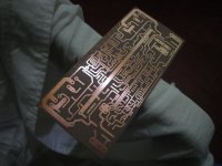
can u share the post 41 pcb layout in pdf.
here all the original files, same one I used to make my amplifier.
Hope to hear your comments soon!
")
Assemble carefully, check solder, check for short circuits. I know PCB is very critical
further steps we may make new pcb
Good Luck
Attachments
hi microsim.
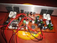
pls see the image.
not yet finished my sphere.
i am working on progress.
i put 11k resistors to 10k+1k in series, and 510 ohm to 330+180 in series, 51 ohm to 47 ohm.
check the led's polarity is correct or not.
i cant find 2.5k preset so can i use 3k preset.
for the mylar caps brown color or green color is good. i mean the tolerence.
what is the out coil turns and gage,diameter.
Attachments
-
 DSC01865.JPG238 KB · Views: 149
hi microsim .
for first powering the amp what is the procedure i have to make?
is it ok bf471,472 instead kf470,469.
You dont have to make any thing, except powering up, and if relay turn ON after 3 seconds, then you put the FUSES.
Regarding transistors, you have to check data sheets for both and compare it!
hi microsim.
i connected the amp with 10ohm/1w resistor instead fuses.
after three second the relay works and led light on.
so what is the adjusment of the preset.
thanks for ur cooperation.
Very Good Results until now.
Idle Current values should be between 120 ~ 140ma, I assume you know how to adjust it.
Tell me if you can hear clear sound from the amplifier.
hi microsim .
i am sorry my power supply voltage is 47vdc. so any changes to make for properly work.
1- You have to compare the PCB you have made with the LAST one I have posted
2- +-47VDC is OK with the amplifier, but lower power you will get
3- You should inspect your PCB, transistors directions, Solder, etc..
I dont know the exact reason for the problem, tell me if you can hear sound or not