TL494 schematic by 0xff

expressel

New member
Hi,

I designed this circuit with discrete high side bootstrap driver. I decided not to use IR2110 or transformer gate drive.
I dont know why but I hadn't luck with IR2110.

Lets start with the controller part:


I used the first error amplifier for feedback regulation and the 2nd for current limiting.
I supply the IC with 15V zener diode feeded from 320V with two 68k 2W resistors in parallel. I think this is enough like its in IR2153.

Now the power part:


Silvio

Well-known member
Hi,

I designed this circuit with discrete high side bootstrap driver. I decided not to use IR2110 or transformer gate drive.
I dont know why but I hadn't luck with IR2110.

Lets start with the controller part:


I used the first error amplifier for feedback regulation and the 2nd for current limiting.
I supply the IC with 15V zener diode feeded from 320V with two 68k 2W resistors in parallel. I think this is enough like its in IR2153.

Now the power part:


It looks good how about some tests and pics of the wave forms produced. The goal is a good drive current with a nice square and fast rise times.
What is the intended power of this smps? I asking this because at higher than say 500w an auxiliary winding will be necessary to feed the 15v drive circuit.
 

expressel

New member
Thanks, I'll do a test when my new scope arrive. The intended power is 250W, I have many transformers from computer ATX supplies.

I asking this because at higher than say 500w an auxiliary winding will be necessary to feed the 15v drive circuit.

You mean that the zener can't provide the neccesary current for the gates?

Oh I forgot to draw a snubber.
 
Last edited:

Silvio

Well-known member
View attachment 6842

The high side, i should go like that.
Or just on the ir2153.

Hi Kanon the high side gate must be isolated from the low side gate and the ground for the high side drive must be in the centre of the half bridge. The bootstrap capacitor will have to give all the current needed to the high side.

The ground path of the bootstrap capacitor will be when the low side fet conducts this will create a path to ground hence it will charge up between each cycle. This capacitor must not be too large as according to the frequency used it has to be fully charged. The higher the frequency the less time it has to charge. A value is set for correct operation.

For a frequency between 50 and 100Khz a value of around 0.5 to 1 uF will suffice. It is important that you use a good quality capacitor here as this will take quite a beating. It could also be of a non polarized type like polypropylene film capacitor or an electrolytic of the gold or silver type marking with low ESR

Total isolation can only be created with a gate drive transformer as the primary of the gate drive transformer is isolated from the gates of the fets. Another method is to use 2 separate drive chips fed from 2 independent 15v aux supplies thus one aux will have a common ground to the high voltage ground and the ground of the other aux will have a ground on the centre of the half bridge. This will become more complicated and is only used when there is the need of high gate current.

However for your need a 0.47 uF bootstrap capacitor will be enough for the smps you are building as here you will be using medium power fets like IRF840 or IRF740.
 

Silvio

Well-known member
Thanks, I'll do a test when my new scope arrive. The intended power is 250W, I have many transformers from computer ATX supplies.


You mean that the zener can't provide the neccesary current for the gates?

Oh I forgot to draw a snubber.

Yes the resistor- zener arrangement will provide the necessary current needed in your case for a 250w smps driven from medium power fets.

As for the snubber do not worry about it just see the wave forms across the primary and only include it if needed. If the wave forms are clean from spikes when loaded then you do not need it.
 
Last edited:

expressel

New member
I was waiting for my new scope to arrive until my father told me that he didn't ordered it yet :D

Today I didn't had a work and decided to test the bootstrap high side circuit with my old crappy scope at low voltage - 15V.

I decided to make a notebook adapter for car.

I soldered this schematic and calculated the transformer with ExcellentIT (2 primary turns, 10 turns secondary, I wound 11 turns secondary).

I expected to have 5A consumation with a 4.7 ohm load when I saw that its only 1.2A and the output voltage drops from 19V to 6.2V
Why this happened ? I thinked a lot and didn't figured it. Ideas are welcome.

I used 4x 1uF capacitors in parallel to convert from DC to AC. This is 0.8 ohm reactance at 50khz.

I didn't used snubber because I forgot.

Here's the schematic and waveforms:


This is the high side waveform at the gate:


This is the waveform at the transformer:

 
Last edited:

Silvio

Well-known member
@ Expressel

Your calculations seem ok to me. I think you should try a few things
1) try to take the sense voltage before the output inductor.
2) check the input voltage at load across the transformer primary. See that its not dropping too much here.
3) The wave shape at the transformer primary is not so nice. This could be due to the output inductor. You may have to use a snubber across each output diode to suppress it.
The wave form can be disturbed due to incorrect coupling within the transformer (too much leakage inductance) I know winding 13 strands is not an easy task, try using a copper sheet instead. If you get hold of some copper tape although its thin (you can always sandwich a few layers on top of each other) is another alternative to copper sheet for the primary windings.
4) Try to cover the whole width of the bobbin with the windings for good coupling
Lastly I know sandwich the secondary between the primary is not an easy task if you are using wire strands side by side. However you can bundle your primary wire in 4 bundles of 3 wires each making a total of 12 strands. here you will have 4 bundles side by side to handle during winding. Check that they will fit in one layer.

I hope this will help you solve the problem
 

expressel

New member
@ Expressel

Your calculations seem ok to me. I think you should try a few things
1) try to take the sense voltage before the output inductor. This is not the problem because I tried without feedback too.
2) check the input voltage at load across the transformer primary. See that its not dropping too much here.
3) The wave shape at the transformer primary is not so nice. This could be due to the output inductor. You may have to use a snubber across each output diode to suppress it.
The wave form can be disturbed due to incorrect coupling within the transformer (too much leakage inductance) I know winding 13 strands is not an easy task, try using a copper sheet instead. If you get hold of some copper tape although its thin (you can always sandwich a few layers on top of each other) is another alternative to copper sheet for the primary windings.
4) Try to cover the whole width of the bobbin with the windings for good coupling
Lastly I know sandwich the secondary between the primary is not an easy task if you are using wire strands side by side. However you can bundle your primary wire in 4 bundles of 3 wires each making a total of 12 strands. here you will have 4 bundles side by side to handle during winding. Check that they will fit in one layer.

I hope this will help you solve the problem

I dont understand everything you said.

1) What sense voltage ? i suppose you mean to take the feedback before the inductor.
2) You mean to check the RMS voltage at the transformer primary ?
3) I think i dont need snubbers for the diodes because I saw this in only one schematic.
How to use a copper sheet ?
I have copper tape, how to sandwitch layers ?
4) Is it necessary to sandwitch the secondary between the primary ?

Do you know that I didn't used wire strands and maybe thats the problem.
I used only single wire 0.5mm just for the test. I suppose it has higher inductance and didn't allowed more current to flow at 50khz

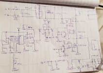
Thanks Silvio, keep the good work and see this amazing schematic I invented -> 400khz switching load because I dont have a load to test my supplys (I only have 4.7ohm 15W resistor and 1x 55W halogen bulb):

Will control it with STM32F103 pcb from aliexpress, with OLED display and rotary encoder. Im little lazy to write the code but I'll skip the bad.

 
Last edited:

Silvio

Well-known member
Hi Expressel using only one strand of 0.5mm and making two turns will not couple enough. You should have known better that you should have used 13 strands according to the Excellent software. The current density with one strand is too high and a lot of voltage drop will occur.
I realized that with only 2 turns on the primary it would be far better to wind the secondary first in the bottom with wire strands and winding the primary on top with COPPER SHEET cut to to the width of the bobbin. This will give you the best practical winding way with good coupling. Keep in mind that a good manufactured transformer with good coupling and minimum leakage inductance is the key to a successful SMPS.

Regarding the feedback yes I meant after the output diode before the inductor.

To gather everything up you should start with a decent wound transformer first then we see if you have further problems later. Just remember that current has to pass through suitable cross section and this will not let you get away with regardless what is the switching frequency. As a rule of thumb you need a current density of 4A/mm for continuous duty while around 6A/mm for 50% duty and 8A/mm for 50% duty helped with forced cooling.

For loads you should visit the rubbish dump or bring in site and look for old heaters. You can acquire some heating elements that you can load with. Old microwave ovens with grills in them will have a nice 1Kw heater usually with 2 120v filaments in series.

Good luck Silvio
 

expressel

New member
I found the problem Silvio, It was the capacitor which converts from DC to AC.
Today I tried with 150uF electrolytic and now it draws 4.4 amperes.
However, this capacitor gets hot and I must use full bridge instead.. ( I dont want to use push pull )
You can use 1uF only for 220V smps-es.
Regarding the feedback, it must be after the inductor, not before. It works far better this way.


Thank you for the assistance. :)

The waveform now is more clearer, look:

 
Last edited:

Silvio

Well-known member
Well that looks better, As for myself I would have used a flyback for a such a converter. It would have been much simpler yet effective.
 

expressel

New member
Flyback, yes, but the idea was to test the high side bootstrap drive.
And also I can't use EI33 if I use flyback. See:


Look what mosfet drive circuit I achieved, 1Mhz freq:

 
Top