TO-247
New member
Hi
i'm going to start my first audio smps.i want use it for my Nmos200 :
http://www.diysmps.com/forums/showthread.php?179-Quasi-s-Nmos200-2-Pair-Edition
+/-40v 5A 2X200W@2Ohm - 600W max power consumption = +/-40v 7.5A per rail
i was read this thread :
http://www.diysmps.com/forums/showthread.php?79-1kW-smps-project-(based-on-MicrosiM-design)
now i'm confused
i don't know which circuit is suitable for me !
IR2153 or IR2110+SG3525
it's because at first , ludo built the ir2153 based circuit but in newer version , he was build 3525+2110 based circuit and result was more reliable.
can anyone help me about this issues ?
there is the latest version of Ludo's IR2110+SG3525 based circuit , please tell me about it , it's OK ?
Attachments
-
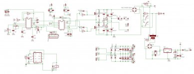 smps v2.1 sch.jpg107.4 KB · Views: 1,814