troubleshooting BASH 750W amp with IR2153

museatex

New member
one of my subwoofers amps had a major failure. I have purchased replacement amps but they are not working well in my setup and I have been trying to repair the old amp.
SMPS is using IR2153 that drives two pairs of 17N40 connected in parallel. I have discovered a blown driver FETs on the primary side along with bunch of other components. Since there is no service manual/schematic I had to create one (there might be errors). I believe I am dealing with shoot through conditions due to insufficient dead time.
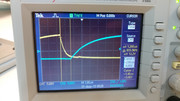
Here is what the dead time on a good working PSU looks like. It is 1.2us as per data sheet. It runs at ~64kHz.


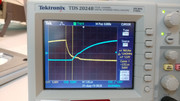
The board I have repaired has dead time of 960ps and runs at ~64kHz. I have tested the circuit with FETs disconnected and it made no difference (Vs connected to GND to enable Ho).


The daughter board that connects to main power supply board has IR2153. Here is what the schematics looks like. It is possible I missed something. The Pin 1 is not connected to anything on the main board (test point?).

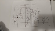
Here is what the main board primary side looks like.

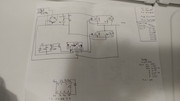
Here is what failed on the daughter board:
Q2 and Q4, R220 (should be 221, I replaced it with 220), diodes D3 and D4 connected to Lo and Ho output pins of IR2153 and 47.5Ohm resistor connected in series with the diode on Ho, IR2153. I created a short while probing around and had to replace 47Ohm resistor.
On the main board I replaced 25V zener diode.
I also measured caps that connect Vb and Vs (pin 8 and pin 6 respectively) on IR2153 in circuit on good and bad board. Good board 107nF and bad board 111.7nf.

Any suggestions how I should proceed further?
 
Last edited:

Silvio

Well-known member
@museatex

Regarding the dead time it is ok usually it is between 1 and 1.2uS well if its just under 1uS like 960nS it does not matter it is still good. The IR2153 has a fixed dead time and does not vary with frequency it stays the same. Please note that the IR2153 has a drive current of about 180mA and I see that is rather limited driving parallel fets. There are better versions of the IR2153 like IR2155 which has a better source and sink current.

ALWAYS PUT A SERIES 100W LAMP WITH THE SUPPLY LINE TO LIMIT CURRENT DURING REPAIRS AND TESTING.
(YOU CAN PUT IT INSTEAD OF THE FUSE IF YOU HAVE ONE)

Some things that you need to check

1 Voltage at pin1 must never exceed 15v The chip has an internal 15v zener, the feed to this pin must never be low impedance with voltages higher than 15v otherwise the chip will blow. A 15V zener is usually inserted between pin 1 and pin 4 for protection

2 From your schematics I see different drive to the gates one showing just a 10R resistor in series with pins 5 and 7 which to me are too low and considering them in parallel the value becomes 5 ohms this puts quite a load on the chip. I did not see the data sheet of the 17N40 so I don't know the input capacitance. Buy genuine replacement parts as fakes from China will not sustain the current. (UT source is a good place to buy replacement parts.)
However in the second schematic I see a different arrangement. Which is the correct one?

3 I also noticed something else and the schematic is a little bit off I think but I can see that you may have a high frequency soft start as well. This is done that initially a small timing capacitor is seen on the timing circuit and then after a 1 second a transistor will connect a second timing capacitor in parallel with the first one to lower the operating frequency. This is done to limit the current on start up as the transformer cannot give full current at a higher than the designed frequency. The chip does not have a soft start and this will create it.

What failed!

Resistor 221R replaced by 220R still ok

The drive chain from pins 5 and 7 will usually blow when the mosfets blow due to the fets blowing and shorting the gate and drain together thus presenting the bus voltage to these pins.

Regarding the bootstrap capacitor (100nF) a minor difference in capacitance will not affect operation.

Lastly the chip needs a good start up current on pin 1 otherwise it will not give enough current to the fet gates and these might fail. Remember also that the 2153 chip is not really meant for driving high current smps but factories try to limit expenses as much as possible keeping the product at low cost. So you see these will not have short circuit protection and usually a fuse is inserted not to let things catching fire.

You can also google up a bit and see other forums and see what others encountered repairing these amplifiers. I found quite a few on this subject. See also if you can get hold of a schematic diagram this will help you a lot during repair.

This is one of them http://www.xlr8yourmac.com/audio/SVS_750W_BASH_AMP_Repair.html
 
Last edited:

museatex

New member
Thank you for quick reply Silvio. ( @Silvio ) This is very helpful and I really appreciate it. Unfortunately no-one succeeded in repairing failed power supply from what I could grasp searching online. I am not referring to easy failure mode when TH1 is blown/felt apart. At that point amp doesn't blow fuses it simply doesn't turn on. My other amp had thermistor failure previously so I replaced TH1 with better part. Original TH1 had a small crack in it so it was just a matter of time. I will document what I have learned thus far. I am sure it will be helpful to someone at some point. The same daughter board is used in other amplifiers with slight component nominal changes.
I had the amp tested and currently listening to it. It is functional though I was worried about the long term reliability. The time will tell. 4 amplifier failures so far during the life of these subwoofers. Horrible reliability. Are you recommending swapping IR2153 with IR2155? Is this a direct drop it? I purchased parts from mouser, so ended up blowing 17N40 FETs and decided to buy them on eBay from US distributor instead. I will avoid Chinese sellers as per your recommendation.
1. When I was powering daughter board I had to supply more than 15V to get it started. Then I was able to lower the voltage. With voltage below 15V the circuit simply won't start. The internal zener is actually 15.6V.
2. The design of this amp has 10 Ohm gate resistors for each FET and 332 Ohm on daughter board, so it is 337 Ohm total. Also there is diode with 47.5Ohm resistor in parallel with 332 Ohm to discharge gate capacitance. I don't know how to calculate discharge time with diode in parallel with 332 Ohm resistor. If the diode wasn't there with 47.5Ohm series resistance the dead time required will be incredibly long and 1.2uS nor 960ns wouldn't work (at least based on my calculations). 17N40 datasheet Qg 45nC.
3. You are absolutely correct about one cap being shorted to run at different frequency.

Need to correct the first post. There was another transistor blown I forgot to mention, it is the one on main board connected to 25V zener.
 

Silvio

Well-known member
@museatex

See if you can get hold of a schematic otherwise I will not fully understand what you are saying. You are seeing things in front of you and I cannot see anything. Google up and search for it.

I would like you to see the datasheet of the IR2153 and also the IR2155. The IR2155 is a better chip which has more drive current than the former chip 2153. Yes it is a direct replacement, please also note that the chip will start to oscillate at around 10v. This also has a micro power start up. Usually a start up resistor followed by a 10 to 12v zener to stabilize the output voltage is fed to pin 1. As the smps starts oscillation the auxiliary winding fed from the main transformer will take over and supply the chip at the required voltage or around 14-15v or so. The start up will shut off due to the auxiliary feeding the chip at a higher voltage.

Regarding the comment that they will simply don't start well I advise you to disconnect the amp from the power supply even by removing the mosfets etc and see the the smps drive is working on its own.

Regarding the amplifier itself well these are a bit finnekey and have to be perfect otherwise they blow. See if you can operated from a bench power supply usually at around 20-0-20 or so and using current limit not to let things burn if there is something not right. You can then check the waveforms at the output usually the base frequency is around 240Khz and take a look with the scope before and after the output filter. Check also what is going in the gates of the 17n40. See that they have enough drive voltage going through them.

One last thing you should check is for dry joints or faulty vias in the pcb. I encountered this problem quite a few times and the amp will blow for no reason. If you are checking with a bench supply and current limit then you can warp the pcb at various places to see for any changes. It is quite a task to localize the faulty via or dry joint. Once you find it the problem will disappear.

Regards Silvio
 

museatex

New member
@silvio

Unfortunately schematic is not available for this product. hat is why majority simply replace these amps when they fail. I have checked through my channels and people that designed this amp have long gone from Bash. If my amps fail again I will look into switching to IR2155. I have programmable AC supply at work my original plan was to reduce the max Current instead of using the bulb or use 2 channel DC supply as you suggested. I ended up plugging it into kill a watt plug to monitor voltage.

Thanks again.
 
Top