XR2206 digitally controlled function generator

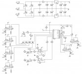
I am working on a digitally controlled XR2206 based signal generator. The core oscillator schematic is attached. It can do sine, square, sawtooth,triangle,duty contolled square wave,FM,AM and voltage contolled frequency sweep the kits don't give you all this, only the basics.

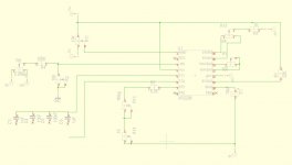
The plan for the time being is to control the XR2206 using a 16F628A and relays plus leds for indication. As for the frequency, duty and amplitude control i will use potentiometers for the time being. If program memory is available to control the generator using USART from a pc application.

Am also considering a more complex approach afterwards using the following:
16F877A pic
USART- PC application to control pic
LCD to display information
CCP as frequency counter
Digital potentiometer for amplitude control
ADC to monitor output amplitude
DAC to set frequency and duty values

I'll start with a project board version with a 16F628A and see where i end up. I am right now building the algorithm for the pic control and testing it on my 16F628A dev board before integrating both together
 

Attachments

  • XR2206.JPG
    XR2206.JPG
    80.6 KB · Views: 139
The pic relay algorithm is working fine and i have been able to get dc voltage using either PWM or R2R ladder DAC. I prefer to go the PWM way its more annoying to setup but uses less I/O pins. I will have to get my duty cycle variable , measure and apply it to the XR2206 to continue. 16F28A seems to be only good for experimenting for this project. A 16F877A seems to be the only way to go
 
I have been able to conrol the voltae defining frequency for the XR2206 by using the PWM output from my 16F628A the voltage levels are -1.2V for the lowesr frequency and -5V for the highest frequency.

Tranforming pwm from pic to voltage can be easily done with the following: http://www.microchip.com/stellent/idcplg?IdcService=SS_GET_PAGE&nodeId=1824&appnote=en011079 app note from Microchip and filtered by a single or double pole RC filter

My pwm frequency is 50KHz for the time being and filtered by a 100K and 1.5nF caps

Now since XR2206 needs negative voltage the following link gave the solution: http://www.edn.com/design/integrated-circuit-design/4368224/Voltage-inverter-employs-PWM and has to be placed before the RC filter.

The next things i need to take care of is an opamp to buffer the output current due to loading and limiting the duty cycle values so as no to go below -1.2V.

I will post the updae schematic as i get moving
 
Updated schematic

Attached is schematic without pic as i'm moving to a 16F877A. One thing to note here is pin 8 has to be held at -0.75V(normal operation or ~98% duty cycle) and can be incresed to ~-1V for 0% duty cycle.
 

Attachments

  • Capture.JPG
    Capture.JPG
    105.7 KB · Views: 105
My 16F877A dev board is ready and tested. I have to port my code from 16F628A to the 16F877A and also build a C# app that should interact with the serial port to control the signal generator. I will send pictures of the dev board. The good thing about the 16F877A is that it has two PWM outputs which is good since it will replace the potentiometers i needed for setting the frequency and PWM and everything will be fully controlled from the pic. I also need to take the XR2206 out from the bread borad onto something more firm like a strip board to have stable connections to be able to carry on the work.
 

smps_fan

New member
This is a nice project I´m looking forward to your nice and cool function generator ! I have that XR2206 IC too and need a very cheap function generator. As I´m new to PIC microcontroller could you say what´s the easiest way to flash a assembly or c code into a PIC ? Do you share your code and last schematic after it´s working ? Good luck and thank you !

Best regards your
smps_fan
 
Hi to flash code into the pic you need a programmer i use a pickit3 clone that does the job well. If you are looking for a cheap solution there is a schematic on elektor's website using mechanical push button, its not to discourage you but it will get complex with pic as you need to use the digital outputs and PWM to set frequency and PWM.
 

PaulC

New member
Hi zeus_threat

Hi zeus_threat
i have one of these xr2206 and would very much like to follow your project.
would it be possible to post or send me the files PIC, PC Interface also schematics..
sound like a excellent project..
 
Just an update on the project I did some test with CD4066 and without going into extreme details it is not appropriate for this project. I will have to stick with relays. I am also trying a more accurate variation of the voltage control in order to get a more accurate frequency dial. I'll keep posted
 
Am back again with more bad news. I did some other test with CD4051 to control the switching of capacitors for frequency and wave switching. Capacitors above 10nF are too high and buffering is a real complication. As for some function switching the internal resistance becomes too high. There certainly is the 74HC4051 but I doubt it will be any better. Relays seem to be the only option. On a side note I did start working with an AD9850 and the results are quite good. There is also the AD9833 which is closer to a function generator
 
Back again with some better news I got the XR2206 switching ready for digital control. To solve the issue I had to use +5v and -5V to power the XR2206. I have used a CD4051 for switching the caps powered between +5v , -5v and Ground( yes it has a ground pin). For all other switching (e.g sinewave , squarewave , pwm) I have used a CD4066 again powered between +5v and -5V (no ground connection). for the frequency control I have used an LM324 connected between +5v and -5v (no ground) a 2sc945 and a 1K resistor acting as a variable CCS between 0 and 2.5V(WRT -5V). What I need to do next is use a microcontroller between +5V and Ground level shift the DAC(PWM in my case) from +5V/GND to +5V/-5V and feed the LM324 with a vref. The same level shifting will need to be applied to CD4051 and CD4066. I am also thinking optocouplers I will see and keep posted.
 
Top