ETD49 Overheating

wally7856

New member
+-80V >> 7A
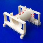
Any of these 3 wires will work for your secondary with just one strand, if they will fit. I got the 1.386" dimension from a etd59 drawing i found on the net, your bobbin will have slightly more or less room.

1.386" winding width on bobbin / 22 total turns = .063" for bundle

11+11 turns of one of these wires.

1.5mm .0590" bare, .0618" dia, 3,487 Cmils
15awg .0571" bare, .0603" dia, 3,256 Cmils
1.4mm .0551" bare, .0578" dia, 3,037 Cmils
 

wally7856

New member
Badboy i made a few mistakes.

I recalculated the secondary turns using best guess voltage drops, it looks like i cut it to close with 11 turns.

starting with 226vac
ACV drops
diodes 2v

DC drops
igbt .5v
transformer 1v
inductor 80mOHM .56v
misc drops traces 1v

It looks like 12 turns will just make 80vdc and the input would have to have large input caps to hold the voltage up.

Also we do not have to use wire as large as i thought. I forgot that the output power is divided by the two power rails +-. So each power rail has to supply 7A / 2 = 3.5A

The good news is we will not have any trouble making things fit.

Here is a pdf from IR explaining the power supply for audio. This is the one i re-read every now and then to refresh my memory.
 

Attachments

  • 12v car audio power supply IR design details 500W iraudps1.pdf
    738.3 KB · Views: 51

wally7856

New member
Bobbin window width = 42mm = 1.889"

This is a big difference from the bobbin i found, are you sure that number is not the outside of the bobbin?
 

wally7856

New member
Badboy take a look at this, we may be using the wrong currents.

"my secondary winding will need at least two layer to fit in bobbin because I want to get +-80v ( for two 400W class AB amp) and +-50v (for two 200W Class AB amp) "

IR AP note page 28.
Total output current = 800W/80vdc = 10A
10A / 2 = 5A +rail and 5A -rail
This calculation does not include efficency.

Total output current = 400W/50vdc = 8A
8A / 2 = 4A +rail and 4A -rail
This calculation does not include efficiency.
 
IR AP note page 28.
Total output current = 800W/80vdc = 10A
10A / 2 = 5A +rail and 5A -rail
This calculation does not include efficency.

Total output current = 400W/50vdc = 8A
8A / 2 = 4A +rail and 4A -rail
This calculation does not include efficiency.

It's true

but the efficiency in class AB is about 60% to 70%
and it demand about 7rms current in each channel

800W x 4 = 3200
root of 3200 = 56.5 (RMS voltage drops on a 4ohms load)
56.5 / 4 = 14.1A ( RMS output current)
14.1 / 2 ≈ 7A ( RMS current for each channel)
 

Jagd.Panther

New member
between 2 primary's you can only have one secondary layer. Unless you have very very good litz wire. I think Microsim paid $3000.00 for a roll of litz wire.
Can you define "very very good litz wire"?

badboy
If you have two main secondaries (one +/-80V and one +/-50V) you can try to split the primary in 3 piecies instead of 2 and ''sandwich'' them into the transformer. I do not know if it is good or bad idea but it may work.
What current you are expecting for each of the secondaries ?

1/3 - primary
+/-80V secondary
1/3 - primary
+/-50V secondary
1/3 - primary

^^^^ it's asymmetrical, I wouldn't use such layout.

1/3 - primary
½ +/-80V secondary
½ ±50v sec
1/3 - primary
½ ±80v sec
½ ±50V secondary
1/3 - primary
Should be better. However before going with this layout I'd try "classy" ½ pri - sec - ½ pri layout.

Your schematic does not show any output inductors. You must have an output inductor for your circuit to work properly.
They aren't needed for unregulated DC/DC converters.
Most important spec for output capacitors is there ripple current rating and there ESR.
Very true.

Badboy i made a few mistakes.

I recalculated the secondary turns using best guess voltage drops, it looks like i cut it to close with 11 turns.

starting with 226vac
ACV drops
diodes 2v

DC drops
igbt .5v
transformer 1v
inductor 80mOHM .56v
misc drops traces 1v
0.5v for IGBT is very UNREALISTIC. I bet 95% of IGBT's have Vcesat of 2v ±0.5v (operating at close to max. rated current)
 
Welcome back "Jagd.Panther "
Do you also think that the two layer secondary(proximity effects) is the reason for hot windings?
It's not possible to wind the secondary in just a layer with more than 20 turns in primary (because I need about the same turns as primary to wind the secondary for getting +-80 volts)
I can't go higher than 50khz because the IGBTs gets really hot
The flux density also can not exceed 900 gauss if I want less than a 20"c temperature rise in idle

So to achive these I can wind the transformer like this:

Primary = 30 turns
Secondary = 32 turns

These turns gave me about 800 gauss at less than 50khz

Am I wrong anywhere?
 

wally7856

New member
Badboy if you really need the 7A then the winding's will not fit on one layer. Maybe you should go back to your making two smps idea.
 
Hi guys

I'm working on the transformer and will solve the problem

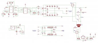
Meanwhile I'm having a problem with C9 (coupling cap)
it's making a weird noise and gets really hot and I think it's normal and it's because of the current passing through it at high power
is it ok to parallel two or three cap to obtain same capacity but with higher current rating, like:
3 x 330nf
or
2 x 470nf

111111.jpg
 

Jagd.Panther

New member
Welcome back "Jagd.Panther "
Do you also think that the two layer secondary(proximity effects) is the reason for hot windings?
I doubt. I suggest you to measure DC resistance of windings and Rth of the transformer first.

To do that:
- since both pri and sec are rated for about the same max current, connect pri and sec in series.
- connect pri & sec to 12v power supply (or a car battery) in series with 55w or 65w lamp (or even two lamps for higher current, would be even better). that will give ~4.5 or 5.5 A current (or twice of that).
- wait for 15-30 minutes, measure temperature of the transformer.
- measure voltage drop on pri & sec winding. Use that to calculate DC resistance and power losses (I*U).

Once you do that you can compare DC losses and AC losses.
 

Jagd.Panther

New member
What do you think is the best topology to wind the transformer windings?
It depends on many factors. If you need ±50V and ±80V for an audio amplifier I'd add a tap to 80v winding. Or changed bus voltages to ±45v and ±90v for flexibility (you can wind sec's in using for windings in parallel, for example).
With regard to winding layout ½ pri - ½ sec ½ sec - ½ pri it's widely used in industry, I doubt it's that bad.
 

Jagd.Panther

New member
Hi guys

I'm working on the transformer and will solve the problem

Meanwhile I'm having a problem with C9 (coupling cap)
it's making a weird noise and gets really hot and I think it's normal and it's because of the current passing through it at high power
is it ok to parallel two or three cap to obtain same capacity but with higher current rating, like:
3 x 330nf
or
2 x 470nf

View attachment 5552
1st, I second Wally, it's OK to parallel many caps. You can build a cap with 2x higher current, 2x voltage rating by connecting 4 caps in 2s/2p manner.


2nd, to put it simple, the value of this in cap hard switched / non-resonant SMPS depends on maximum output power. The higher the output power, the higher the value of this cap should be.

For example, let's say we are OK with 10% voltage droop on this cap.

- We have half bride smps
- running from 230V mains
- 1400 W output power
- 50 kHz switching freq
- 0.45 duty cycle per one switch, 0.9 total.
- 80% efficiency
- <10% of voltage droop on this cap is acceptable.


then:

Rectified voltage: 230*1.41 - 2v drop on diodes - 2.5v drop on IGBTs = 320V.
Primary current: 1400W/0.8/0.45/320V = 12 A.
Effective switching 1/2 period (when either IGBT is conducting): 0.45 / 50 kHz = 9 uS
voltage droop max: 320V/2*0.1 = 16v.

Minimum value of the cap is: 9 us / 16 volt * 12 ampere = 6.8 uF
 
Last edited:

Jagd.Panther

New member
What do you think is the best topology to wind the transformer windings?

I tried to estimate copper loss for your transformer, got over 10W. It looks way too high.

One of the easiest option is to ditch that home made litz and use thicker wire. Do you have thicker magnet / enameled wire available? Like 0.8 0.9 1.0 1.1 mm or something in that range?
 
I tried to estimate copper loss for your transformer, got over 10W. It looks way too high.

One of the easiest option is to ditch that home made litz and use thicker wire. Do you have thicker magnet / enameled wire available? Like 0.8 0.9 1.0 1.1 mm or something in that range?


I'm sure that the problem with my transformer is nothing but copper loss as well

I want to run the transformer at 50Khz or 40khz and I think I'm not suppose to go lower than AWG 23 (0.57404 mm diameter ) due to skin effect (100% skin depth)

I can get another wire If it is necessary
 
another thing

how much circular miles per amp is good to have a cool winding?? 500 is ok??
because I now wind my transformer with density about 375 and I think this is the cause of transformer overheating
primary = 36x0.25mm
Secondary = 30x0.25mm

0.25mm = 100 circular mils

primary= 36x100 = 3600 CM
Secondary = 30x100 = 3000 CM


Primary RMS current is at least 12.5A at full power (with 80% efficiency)
and that result in >>>> 12.5x375 = 4700 CM >>>> 4700/100 = 47 strands of 0.25mm wire with density of 375
and with 500 for density we have >>>> 62 strands of 0.25mm wire


Secondary RMS current is 8A
with 375 CM >>>> 30 strands of 0.25mm wire
with 500 CM >>>> 40 strands of 0.25mm wire

am I right???
 

Jagd.Panther

New member
another thing

how much circular miles per amp is good to have a cool winding?? 500 is ok??
It depends.

The best answer would be: if you want to limit temperature rise of a winding you have to limit copper loss for that winding.

For example, if you do a test with DC current flowing through the transformer then you can find that (just an example, I'm trying to guess) it takes 8 watts to rise the temperature of the windings by +30degC. With a fan, it takes 15 watts for +30degC rise.

Then if you have just two windings you can split copper loss equally between the windings.

Taking into account pri and sec voltage (turns), current, copper resistance and winding length (you can use MLT aka mean length per turn) you can easily calculate minimum wire area.

Example: you know that you have 8 watts for copper loss to spare, you split it 50/50, 4 watts per primary. 1500 watt, 150V for a primary, that's 10A. A maximum resistance for primary would be 0.04 Ohm. For example primary is 20 turns, and MLT for the core/bobin is 10.9cm, so primary winding length is 220cm. Now you have to calculate wire area for resistance less than 40 mOhm for L=220cm.
 
Last edited:
Top