Jagd.Panther
New member
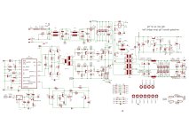
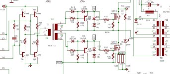
Which IBGT's are you going to use? What frequency?just found this at a forum in edaboard . i wonder if it will drive the igbt or it is a better way to use gdt method
View attachment 5564View attachment 5565
Which IBGT's are you going to use? What frequency?just found this at a forum in edaboard . i wonder if it will drive the igbt or it is a better way to use gdt method
View attachment 5564View attachment 5565
Which IBGT's are you going to use? What frequency?
Hi Stewin, Zeners will do nothing with switching performance. IGBTs tend to be slower than MOSFET's, this translates to higher switching losses.
What you should be after is switching IGBT's off with a negative voltage, like 2-4 volts.
any schematics sir ??
attaching examples of GDT driver circuits. Complementary BJT Emitter Followers vs Mosfets.


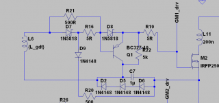
Post schematic/pico.k thanks sir . i use ee16 only and 70khz .that is rt-10k ct-1nf discharge 33ohms fets are irfp460.
How many of these do you have? Are you ready to buy extra IGBTS when yours blow up (that could happen)?( i also have these igbtsIRGP30B120KD-E , IRG4PH40UD2 , K30N60 , IRG4PF50WD , k40T120 , IRG4PC50U , IRG4PC40U ,)
Are you set on HB? There are many options, for example use voltage doubler and 900-1200V IGBTS, full bridge, two switch forward, etc. What kind of power ferrite cores do you plan to use?what should i do sir i needed power like 3500watts half bridge?? which of the above igbt should i use or should i parallel irfp 460??
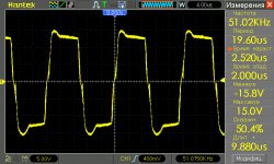
well run the simulation, open post #99, .asc file for LTSPice is therealso please post gate wave form pictures of your above gate drive schema.


 View attachment gtG smps lp small schematic.pdf
I tried with EEL 19 cores salvaged from ATX PSU. Leakage inductance was kind of high so I opted for a toroid core instead.has anyone actually used an EE or EI core as GDT?
EMI filters often have high-perm coresall my magnetics are from salvaged parts and i just couldnt get toroids...
What kind of E-cores do you have? What is targe SMPS sw freq/co?any hints and tips for a EE/EI GDT? info all over the internet point out abandoning it and buy a toroid.
Source an oscilloscope , with at least 5mhz bandwith. It's a must if you deal with SMPSby the way i dont have a scope. i only have a freq/duty counter.
i use etd70 ,ee55 , er42 cores, i can get my hands on few other igbts same value as above but irfp460 are plenty and easy to find.
i am not fixed on hb but having tried it without protection , with unstable generators and also unreliable ac mains power supplies , i tend to like its robustness and reliability, i haven't tried other topologies.
I did measure AL for EE(L)16/19 cores I found in ATX PSU. I can't find my notes but IIRC the material had perm in 2000-2500 range.i have the typical ATX triads; the EE16/19 base drive; the EE19 of the aux supplies [sometimes an EEL19]; and the big EE/EI/EER 28/31/33/41.
EMI filters come in various shapes (E-cores, C-/U-cores, toroids) and materials (including low & high perm ferrite). You have to test itemi filters you mean the common mode chokes? i have some. theyre large in overall size but the legs are very skinny.
it's unlikely. However you still can use it for a GDT. Obviously you have to rewind it and add another dedicated current transformer (most ATX PSU with BJT use proportional base drive and base-drive transformer serves as a CT).could the base drive trafo be hi-perm material too?
Use a heatgun (may require 100-150 degC and patience) or soak them in acetone (may take up to few days)theyre quite hard to disassemble though with all the potting.
If you are designing an SMPS or building one you have to have such tools as RLC meter (to assess Lm, Ls, perm, parasitics, etc) and an oscilloscope (ideally with high bandwith, ringing due to parasitics may easily fall into 10+++ MHz range). Otherwise a lot of guesswork and brute force engineering (trying over and over again all of the possible options) may be required.most of these ATXs work up to 30-35kHz tops. i made some smps that dont need GDT running around 60-70kHz [IR2153, UCX84X and similar]
using a GDT with an SG3525/TL494 is a bit new to me.
also, ive tried running HB ATXs up to 50kHz with no noticeable adverse[violent] effects but i still retained the BJT halfbridge. im quite sure i have to rewind it for use with MOSFETs.
I probably had the same issue while I was trying to make half-bridge with TL494. I used little EE core from ATX PSU, think it's called base drive transformer. I winded 4x 15 turns, 2x primary (push-pull drived directly from TL494, also used anti-parallel diodes for output transistors) and 2x secondary. When I turn on auxiliary supply circuit drain a lot of current and output waveform's look very similary to your's. So I tried another core - FT82-43 which worked. So I also tried to use full bridge driver (4transistors) for EE core and it started to wok. So IMHO, there is a issue during starting up a circuit. During this time output transistros may not switching with defined duty cycle and core get's into saturation before circuit stabilise. You may try to cut the VCC from your GDT then start circuite and connect it back. IMHO it should work.
Or manually put error amplifier into high state for a few seconds after startup circuite.
hi allAlso it's a good idea to install 15-18v zeners back-to back to protect the gate (connect them to source of the mosfet and emitter of Q1 on the attached schematic). C7 should be ceramic one, in 0.1-1u range.