You are using an out of date browser. It may not display this or other websites correctly.
You should upgrade or use an alternative browser.
You should upgrade or use an alternative browser.
1kW smps project (based on MicrosiM design)
- Thread starter ludo3232
- Start date
Hyper2283
New member
I manage to power up my smps, after mosfets, bridge, some diodes, Ir, SG, blow up. Now with 4x500 w halogen lamps (2 on pozitive rail, 2 on negative rail), voltage drop from+- 92(184 Vc), to +-88 Vc , curent 5 amp. I think it's ok, but at that load, ETD 49 make a noise, like something welding. I tried to gather better transformer, but without results. From what is this noise? Core reaches saturation? It may be due to imperfect contact with the load? I connected my class D 900w amplifier, and ETD 49 make that noise when I increase the output power. How can I stop that noise? Thanks
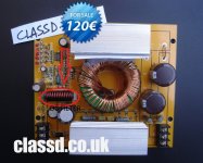
Hyper, i have problem with noise before while running ir2110 + SG3525, can be solved put Ferrite DC Filter for each rails +/- vdc like attachment. and for the buzz thing from the transformer i think u need to correct the winding for the transformer and saturates i think yes.
Attachments
-
 CAR-SMPSX700.jpg145.6 KB · Views: 408
I manage to power up my smps, after mosfets, bridge, some diodes, Ir, SG, blow up. Now with 4x500 w halogen lamps (2 on pozitive rail, 2 on negative rail), voltage drop from+- 92(184 Vc), to +-88 Vc , curent 5 amp. I think it's ok, but at that load, ETD 49 make a noise, like something welding. I tried to gather better transformer, but without results. From what is this noise? Core reaches saturation? It may be due to imperfect contact with the load? I connected my class D 900w amplifier, and ETD 49 make that noise when I increase the output power. How can I stop that noise? Thanks
Hyper2283
It will be impossible to solve problems without showing things like, Waves, Your setup, transformer.
and all other details of your work.
I have to see these things before giving you comments about that problem, I had that into my first SMPS I ever made.
Waiting your comments
regards
Hyper2283
New member
Hyper2283
It will be impossible to solve problems without showing things like, Waves, Your setup, transformer.
and all other details of your work.
I have to see these things before giving you comments about that problem, I had that into my first SMPS I ever made.
Waiting your comments
regards
Microsim
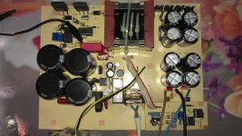
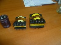
Here's my setup, 3.11 ver smps pcb and ver1 protection card.
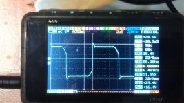
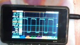
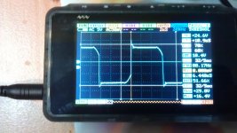
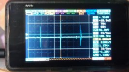
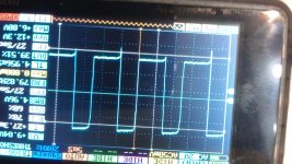
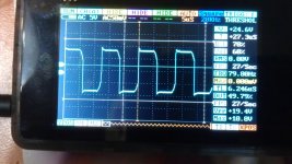
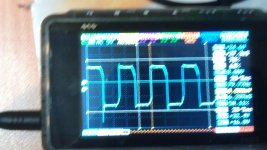
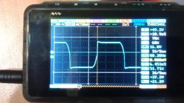
ETD 49 with 11+11 turns primary and 13+13 turn secondary to obtain +-94 Vc. I attached following snapshots: my setup (pictute 59), signal on SG (picture60), signal IRFP460's (62,63), signal on primary (half primary-picture 64, the other half primary-65), signal on secondary (half secondary-67,the other secondary-68), and DC noise on smps output (picture 69).
For ETD49 I used 0.3x8 wires in parallel, and 0.3x10 wires for secondary (home made litz wires).
Thanks.
Attachments
-
 IMAG0066.jpg207.7 KB · Views: 126
 -
 IMAG0062.jpg181.7 KB · Views: 151
 -
 IMAG0067.jpg185.3 KB · Views: 100
 -
 IMAG0059.jpg254.2 KB · Views: 331
 -
 IMAG0060.jpg182.4 KB · Views: 105
 -
 IMAG0069.jpg189.7 KB · Views: 62
 -
 IMAG0063.jpg259.1 KB · Views: 61
 -
 IMAG0064.jpg213.3 KB · Views: 57
 -
 IMAG0065.jpg200.7 KB · Views: 54
 -
 IMAG0068.jpg203.8 KB · Views: 54
Hyper2283
New member
Microsim
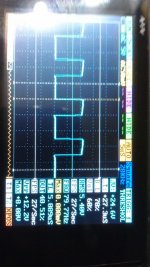
As you can see signal from Sg shows that duty cicle is 40%, but on both mosfets is 50%, and same on primary. Am I wrong? how do I know how to set Rt and Ct. By changing Ct, can I adjust duty cicle? Why is 40 % on Sg and 50% on primary? Where must be measure signal (duty cicle) to be set corectly?
As you can see signal from Sg shows that duty cicle is 40%, but on both mosfets is 50%, and same on primary. Am I wrong? how do I know how to set Rt and Ct. By changing Ct, can I adjust duty cicle? Why is 40 % on Sg and 50% on primary? Where must be measure signal (duty cicle) to be set corectly?
Microsim
As you can see signal from Sg shows that duty cicle is 40%, but on both mosfets is 50%, and same on primary. Am I wrong? how do I know how to set Rt and Ct. By changing Ct, can I adjust duty cicle? Why is 40 % on Sg and 50% on primary? Where must be measure signal (duty cicle) to be set corectly?
I really dont know the exact reason, TO247 Had problems with this, Please change and make sure that the DT resistors is 100R minimum
Its not OK to have 40% duty
I have also checked my smps, its 50% all the way
regards
TO-247
New member
I have also checked my smps, its 50% all the way
Hi MicrosiM
did you check SG outputs ? because SG's output had duty about 44% , but as you seen in my photos , i measured 50% at Vds of each mosfet !
Regards
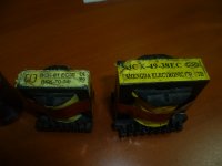
renotrend, I think your transformer taken from flyback psu, so flyback trafo have air gaps which is not suiteable for half bridge application. It can be use but maybe not stable. better get transformer from PC Power supply at least, but the power output will be limited, maybe arround 300-400 watts.