You are using an out of date browser. It may not display this or other websites correctly.
You should upgrade or use an alternative browser.
You should upgrade or use an alternative browser.
Class D 200 Wrms with 2 mosfet cheap
- Thread starter norazmi
- Start date
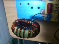
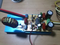
here i can suggest for you, make sure driver transistor is BD139/140, i`ve seen that your R15 u have couple resistor there, what value they are? check it back, another symptom that might cause mosfet overheat is bad filter caps, change the 1uf filter caps at output. The core etd49 is overkill actually, lower your turn to 22-24 turn. then post your result here.
For testing, taking out filter caps and output inductor coild, dont connect any speaker, and turn your amp on see if u still have overheat at mosfet.
regards Azmi
Hi Norazmi
Sorry late to post ,little busy
I have found the problem my amp are ic socket and
Fet output p-ch is defect measure with multimeter is good
But in cuircuit is defect . Now my amp working normal ,good sound all of audio frekuensi
Btw i want make ucd discret 2 or 3 pair fet out put at 70 volt vcc .which one final schematic
Can u share
THANKYOU Norazmi
Regard,
Renotrend
great to hear that. hmmm for discrete u can use Stewin schematic and hes already post at discrete thread. There is the final schema and u can use 2 pair is enough or if u want spare more $$ u can put 3 pair no problem, but totem pole need to be 2@3 pair per driver hi and lo side. back to the discrete thread so we can discuss there.
Hi sir norazmi,
I just want to know what other parts besides inductor, that may contribute on higher offset that maybe replaced with accurate ones. I also want to know how critical is 470nf polyester and 820pf mica plate. Its hard to find these locally and for know i only use ceramic 50v. Thanks
I just want to know what other parts besides inductor, that may contribute on higher offset that maybe replaced with accurate ones. I also want to know how critical is 470nf polyester and 820pf mica plate. Its hard to find these locally and for know i only use ceramic 50v. Thanks
I used smaller green/blue core cutted and wind single #20 wire, metey says its around 35uH. Now BD is only warm mosfet is dead cool "maybe because of heatsink also", DC offset is -40mv. Coil is hot but can retain touching it up to 5 seconds. The only problem are the resistor "220 ohms", hot. I also noticed that the two 2.2K 1W resistor are hot. Thanks
Last edited:
Stewin output transistor should not hot . check if u use bad output mosfet OR bad output coil winding OR bad output filter caps OR check any driver transistor to mosfet maybe defect. The problem will come alots if ur using recycle component when they r not working properly. I`ve face many diyers problem comes from recycle component, Notice that i`m always using BD139 and BD140 for mosfet driver.
. check if u use bad output mosfet OR bad output coil winding OR bad output filter caps OR check any driver transistor to mosfet maybe defect. The problem will come alots if ur using recycle component when they r not working properly. I`ve face many diyers problem comes from recycle component, Notice that i`m always using BD139 and BD140 for mosfet driver.