classd2008
New member
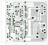
norazmi post your PCB of Discret ClassD. Thank-you.
if u do modification to the gate driver with incorrect value, those transistor will be saturate and will make the amp unstable, lots of spikes.
there is some explanation to this circuit must take a note.
For the UCD design, change the 2n5xx1 by mpsAx2 (save that the legs are backwards) and mosfets for more voltage mosfets ... should not take more modifications - (well, maybe the feedback resistor to have the maximum power with the same input signal).
Now, for all unbelievers who think that this amp can give 200Wrms or more ... just depends on the mosfets. Some quick calculations:
For a power W (rms) on a speaker of R ohms, you need a supply voltage of V = sqrt (W * 2 * R), where sqrt = square root.
The maximum current that will ask the power supply is R = V / R. As the mosfets or totally turned on (fully saturated) or totalmenteapagados (Class D is!) then the dissipation in each MOSFET is pmos = I * I * RDSON / 2 (s / 2 is because alternate mosfets are never turned on both at once, and on average, is half the time on each). Now, specific calculations: For the mosfets used, the RDSON is 0.3 ohms. We take 200Wrms about 4 ohms. little formula According to the above, we need a supply voltage of 40 volts. The maximum current that is going peak to ask the source is from 40/4 = 10A. maximum dissipation of 15W each mosfet will. For the mosfets do not burn overtemperature, MUST go on a heatsink ... Now calculate this sink> assume a temperature the air surrounding the heatsink 50C, the maximum junction temperature of 150C is mosfet.
That will give a thermal resistance junction-ambient (150-50) / 15W = 6.6C / W. The mosfet and has a thermal resistance -joint casing 1.5C / W, so that the thermal resistance remains is 6.6 - 1.5 = 5.1C / W. Assume an extra heat resistance mica and dissipating grease 0.5C / W. This causes the heatsink required for each MOSFET has to be 5.1C / W - 0.5C / W, 4.6C / W. This cooler there, and it is perfectly possible to use. All these calculations are for the worst .. In reality, the audio is not at full power ever, so there is a safety margin far greater than you can believe initially. If only we wanted to get 100W, the heatsink is considerably reduced. If instead of using mosfets specified mosfets with lower RDSON could either increased or reduced power dissipation in the same further. In relation to the coil to the amplifier propose, suggest them instead of a coil, a coil and a capacitor: 10uH coil and capacitor of 1.5 uF (poly) ... The facts are simple ... The cutoff frequency of the filter must be higher than 20Khz, but below the minimum switching frequency of the amplifier (near 500Khz) ... Fcorte = 1 / (2 * PI * sqrt (L * C)), L = Inductanciade coil in henries, C = capacity in farads, Fcorte = cutoff
frequency in Hz, PI = 3.1416. will see that there is an enormous range of values that with that relationship. So I suggest that C = 1 / (2 * PI * R * Fcorte), where R is the maximum resistance of the speaker to use ... I mean, if they are to use it with 2 different speakers, and an 8 ohms, the calculation made ??for 8 ohms. The filter capacitor that is parallel with the speaker, and the coil is in series with the same (ie, the coil conexta the amplifier output with a speaker terminals). For cdo UCD amplifier, coil and capacitor are already part of the amplifier. Finally, the issue of performance: d = 100 * Pparlante / PMOS (d = percent yield, Pparlante, power in the speaker, PMOS = power loss
in the mosfets).
say drivers get hot because the switching frequency is high (1 MHz) and have to deliver large current spikes ... There are 2 possible solutions: Either decrease the frequency of switching (switch C9 by 2n2 - This slightly affects the fidelity at high frequency, but Try it), or less able to use mosfets gate-source (Sliconix any). However, warming did not consider it dangerous. The other is that they hit a disipation on each transistor ... I think that is not worth the trouble.
On the subject of the feedback resistor, you can change if the input signal does not exceed 2v p = p. That is, the 2nd operational output should not exceed in any case 2Vpp. If you have the assurance that the input signal is not going to happen never, 1 Vpp, then make the change, but if not, no. not change the supply voltage of the TL074: This makes the output stage may not go well .. To be exact, The bases of Q1 and Q2 must not exceed the 3 volts, otherwise, the transistors go into saturation, and that's just what we DO NOT have to happen. The saturation dissipate very much power. Everything is
calculated for the issuer in relation to mass up 2.64 volts, which generates a voltage drop on R5 and R6 12V approx.
in relation to the supply voltage. The 12 V zener are a precaution and not because they operate as limiters. Avoid at all costs the saturation of any of these transistors smaller, because they cease to operate at the required speed. The only people who should saturate are the mosfets. If you need to give more amplification, modification are needed for the R16 or R14 and nothing else.
regards.
")
lol.. dude, please refer to Stewin design. Its just the same, i`m also plan to make new one with stewin design.
. and it will be suitable for subwoofer low pass filter only sound.