Class D 200 Wrms with 2 mosfet cheap

stewin

Member
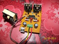
hi norazmi the amp now is cool as cold can be it only gets slightly warm after like 20mins
ferrite core gets warm but managable. ferrite core is 3mm gap t-130-26 30turns
voltage is +/-36vlts .
i added 470ohms resistor in series with r6 and also i added 470ohms resistor in series with r7 so the total resistance r7 is 690ohms and r6 is 690 ohms .
i am using smps i posted in the post no #181
at http://www.diysmps.com/forums/showthread.php?250-IR2153-smps-with-short-circuit-protection./page19

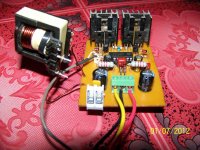
the surprising thing is that the amp is clear , silent (despite of using smps power supply) and has power all the glory goes to GOD almighty . thanks norazmi for all the help may the almighty GOD bless this forum and all the members . thanks guys i will upload photos .
 

norazmi

diysmps Senior Member
Stewin t130-26 is not ferrite, its iron powder material 26 :D . if you face problem with your inductor you can use ferrite core or toroid and make a gap too, if hot become more than 70 C .
 

michelle

New member
hi
greetings you can use EE55 core with 3mm air gap but material must be 3F3 OR 3C90 OR PC40
i use T225-2B core for 3kw from micrometals
warm regards
michelle
 

norazmi

diysmps Senior Member
aha, forget about cutting lol, today i just test output inductor by using flyback trafo taking out from faulty tv, its looks like etd core but i think its EE core. So as we already know TV trafo already have gap at center its about 3-4mm because they use flyback as switching supply. So i just wound today with coil to make lc filter and apply it into class D 200wrms, filter cap i use 0.68 uf, and i measure inductor value is 47 uh. output offset only 10mv with supply +/- 45 vdc. Thats good result and no heat coil, mosfet. I just made this amp today because i have none with me, i just make 11 pcs 200wrms before but they all already sold out :D . Because of too many confusion about making lc filter and other problem, so its easy to get faulty tv trafo.

I`ll take some picture of this amp new one i`ll not keep it longer with me because someone already ask me to buy it. Its good amp for medium use for home and car. No NEED BIG CORE, i just wound this core about 47 uh (awg 18) but its only 1/4 space i use for it, there is 3/4 more free space. So there is too many space with EE32. One more is if u make huge gaps will be decrease inductance , small gaps will be increase the inductance, no gaps of course more inductance. so there is the clue. I dont calculate how many turn i wound with EE32 but i think its about 22-24 turn to get 47 uh.

enjoy all diyers...

regards,
Azmi.
 

stewin

Member
hi all. i have been listening to the amp and smps all day but at normal volumes because it is at home. the clarity of bass for this amp is amazing and the mid too i changed the r6 andr7 470ohms resistors i added to 680ohms.

the small heat sink for the outputs is warm but the t130-26 with gap is more warmer but for the whole day i have had no problems at all with the smps or the amp this is a very silent clear and powerful amp .

the guys with knowledge on simulation please explain how adding the resistors to r7 and r8 have affected the amp . i am puzzled at the technicalities involved .maybe i have interfered with the performance ?
 

norazmi

diysmps Senior Member
here is the pic of new making 200-class D. after finish mount the component i just give +/- 45 vdc and its come alive without any problem. I use very small heatsink and this amp i`ve tested hard no problem with mosfet and coil. :D

regards
Azmi
 

Attachments

  • 100_2180.jpg
    100_2180.jpg
    448.5 KB · Views: 335
  • 100_2179.jpg
    100_2179.jpg
    375.8 KB · Views: 273

stewin

Member
:(:(
hi i changed the r6 andr7 470ohms resistors i added to 680ohms.

the guys with knowledge on simulation please explain how adding the resistors to r7 and r8 have affected the amp . i am puzzled at the technicalities involved .maybe i have i interfered with the performance ?
is the performance affected or which components was i suppose to change in order to reduce output heating ??
according to my ears every thing is o.k also with adding the resistors output heating was eliminated . but i like perfection :) :)
 
Last edited:

norazmi

diysmps Senior Member
to reduce output coil heating u need to change output inductor to ferrire core with air gap or use flyback trafo from tv. The perfection when ur using T106-2 iron powder so there is no need air gap. The schematic same as original and layout also same with what i`m posted at page 1 the different i just draw output to the left and this model for car amp its easy to mount it without inductor at the back :D .

regards.
Azmi
 

norazmi

diysmps Senior Member
output fets also depend on lc filter cutoff, if u read back i already state that nominal cut off is 20Khz. Problem will come when ur using improper inductor :D .
 

t68kv

New member
I already installed mine in computer psu case :D

Driving 15inch 4ohms, Playing Bass I Love You. Low quality picture only.
[video]http://s135.photobucket.com/albums/q148/t68kv/?action=view&current=MOV_0024.mp4[/video]

Note: Primary purpose of fan is to release heat from transformer :D
Secondary, to make the amplifier circuit dead cool including the inductor :) No heatsink on BDs and small to220 heastsink at mosfet.
 

norazmi

diysmps Senior Member
i`ve finish mount this amp with car smps and already test drive very hard yesterday and today, supply rail +/- 45 vdc. i`ll post picture here :D

regards.
 

paskal

New member
First class D

hi there guys. finished my first class d amp. the first in my life hehe :UP:


current draw is at 0.11-0.12A at 30V. stable without any heat output on any FET/BJT. which is quite new to me (coming from class A/AB) :UP:

-snipped, 4 image limit per post-
 

paskal

New member
didn't have any inductance meter on hand. gonna have to borrow a unit from my friend. so i just plugged this coil that i pulled out from a computer PSU.

no idea what the value is. but with the recommended 1uf/250V output cap it gives a consistent 130mv dc offset. pretty safe for my test speakers.

so i plugged the amp into this:

and got some music, distortion free. pretty 'shouty' at first, but the sound do seem to smooth up a bit after 10 minutes. the output inductor now does heat up quite a bit.

for a simple circuit like this, with parts costing less than $10USD it does produce an audiophile grade sound quality.:UP:
 

paskal

New member
Hi

Please can you make a bigger circuit Diagram as it is not readable.
download the pdf in post #13.
the multiple pcbs that are available throughout this thread though have different components, follow the original schematic in post #13
 
Top