You are using an out of date browser. It may not display this or other websites correctly.
You should upgrade or use an alternative browser.
You should upgrade or use an alternative browser.
100W Class-D
- Thread starter Sierra
- Start date
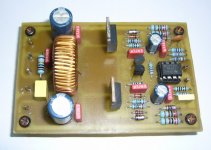
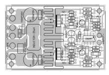
a 100W class-D amp
No schematic was found
Only these
cual es el link
con que impedancia de salida trabaja ?
a 100W class-D amp
No schematic was found
Only these
As far as have been told Class D is the easiest way of PWM amplifing. This is a analog voltage level changer amp to drive the fets and not a Class D. Some reverse engineering is Done. Look at the PDF.
Attachments
As far as have been told Class D is the easiest way of PWM amplifing. This is a analog voltage level changer amp to drive the fets and not a Class D. Some reverse engineering is Done. Look at the PDF.
Mosfets,inverted!!!
correct form:source's to +/-rails
Aucosticraft
New member
To my kowledge pin 2 and 3 needs to be interchanged. As the ic LM393 forms a part of oscillator. And to initiate Oscillations Positive feedback is required. correct me if I am wrong.
Aucosticraft
New member
MalMir, I am not a pro person. All I know that for oscillations to start it needs positive feedback. to check if my basic assumption is correct. I checked with a circuit of one thats in market and so it must be working. I refered to other subwoofer amplifier given here. cause I am not vry sure how the design is going to work I had said correct me . Also if any of you have spice model for LM 393 I would like to try using proteus.
Aucosticraft
New member
tebci
New member
now i am confused
any one tested this 100W D amplifier ?
If not I will make the tested model here soon
http://www.diysmps.com/forums/showthread.php?237-Class-D-200-Wrms-with-2-mosfet-cheap#post1325202125
any one tested this 100W D amplifier ?
If not I will make the tested model here soon
http://www.diysmps.com/forums/showthread.php?237-Class-D-200-Wrms-with-2-mosfet-cheap#post1325202125
well guys have a look at this one http://www.diysmps.com/forums/showthread.php?237-Class-D-200-Wrms-with-2-mosfet-cheap
hilli_billi
New member
Hi,
I think #1t IS class-d. The power fets are an N-type and one P-type. Malmirs schematic is ok. The 35µH coil L1 and C8 are the output filter.
C13, R3, R5 is the feedback to the comparator.
Seems to be an old schematic. Nowadays I would use something like IRS2092.
I think #1t IS class-d. The power fets are an N-type and one P-type. Malmirs schematic is ok. The 35µH coil L1 and C8 are the output filter.
C13, R3, R5 is the feedback to the comparator.
Seems to be an old schematic. Nowadays I would use something like IRS2092.