Hi guys,
I'm electrical engineering student and I'm trying to design 1800W charger with 92V and current limited to 20A.
I'm planning to use UCC28950 TI full bridge controller. My design pretty much base on their reference design,
600W reference design ( http://www.ti.com/lit/ug/sluu421a/sluu421a.pdf )
1.6kW reference design ( http://www.ti.com/tool/pmp6712 )
Desired function :
- Under voltage locked out
- over current protection
- CV/CC output at ~92V - 20A limit
So far so good with UVLO and OCP, I have some questions with Feedback loop design.
Consideration DC sweep analysis of feedback loop, (refer attached files),
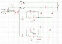
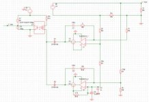
5. file: two-opamp typical CV/CC feedback circuit, Higher op-amp for current loop and lower op-amp for voltage loop.
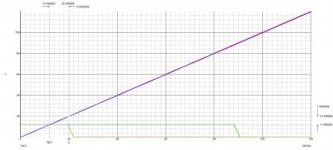
4. file: DC sweep with Rload 10K, and cut-off at Vout = ~90V
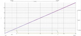
3. file: DC sweep with Rload 1ohm, and cut-off at Vout = 20V => 20A
DC sweep analysis shows, feedback loop is operation as desired. However, I've read at a lot of smps tutorial and reference where they talked about AC response of the feedback and converter.
Questions
(a) Would SMPS operate without considering AC response?
(b) To do AC response, do I have to put Controller, transformer, fet and etc everything to do AC response?
As reference, I've seen in OnSemi feedback and other book that, Phase Margin > 45(degree) @ cross over frequency and DC gain of (20dB).
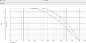
My simulation for AC response is also attached in 1 and 2, it looks like, I'm not doing it right or something is missing.
I've been stretching my head for more than a week for it. I would really appreciate any advice or direction guys. Thank you very much for your time in advance. I'll be looking forward to it.
I'm electrical engineering student and I'm trying to design 1800W charger with 92V and current limited to 20A.
I'm planning to use UCC28950 TI full bridge controller. My design pretty much base on their reference design,
600W reference design ( http://www.ti.com/lit/ug/sluu421a/sluu421a.pdf )
1.6kW reference design ( http://www.ti.com/tool/pmp6712 )
Desired function :
- Under voltage locked out
- over current protection
- CV/CC output at ~92V - 20A limit
So far so good with UVLO and OCP, I have some questions with Feedback loop design.
Consideration DC sweep analysis of feedback loop, (refer attached files),
5. file: two-opamp typical CV/CC feedback circuit, Higher op-amp for current loop and lower op-amp for voltage loop.
4. file: DC sweep with Rload 10K, and cut-off at Vout = ~90V
3. file: DC sweep with Rload 1ohm, and cut-off at Vout = 20V => 20A
DC sweep analysis shows, feedback loop is operation as desired. However, I've read at a lot of smps tutorial and reference where they talked about AC response of the feedback and converter.
Questions
(a) Would SMPS operate without considering AC response?
(b) To do AC response, do I have to put Controller, transformer, fet and etc everything to do AC response?
As reference, I've seen in OnSemi feedback and other book that, Phase Margin > 45(degree) @ cross over frequency and DC gain of (20dB).
My simulation for AC response is also attached in 1 and 2, it looks like, I'm not doing it right or something is missing.
I've been stretching my head for more than a week for it. I would really appreciate any advice or direction guys. Thank you very much for your time in advance. I'll be looking forward to it.
Attachments
-
 5.jpg19.6 KB · Views: 36
 -
 4.jpg18.7 KB · Views: 144
 -
 3.jpg19.9 KB · Views: 29
 -
 2.jpg20.2 KB · Views: 29
 -
 1.jpg18 KB · Views: 117
Last edited: