Dc-Dc 5volt 30amp smps

jayadev

New member
I am trying to build a 12volt to 5volt 30 ampere dc-dc smps.

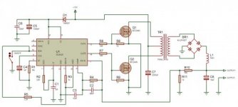
I have used Sg3525 as switching IC and IRF3205 mosfets and MBR3040 output diode. Switching output is around 55khz.

When I test the circuit at minimum load output unable to sink full current , the ouput voltage drops down to 3.5 volt at .25 ohms resistive load.

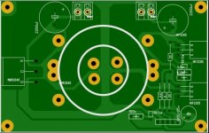
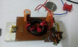
Below is the mainboard PCB which I used. Torroid is 44 mm dia ferrite core with 5 turns primary 3x1mm wire and 2 turns secondary 4x1mm wire.

Please advice why voltage drops considerably at low resistance and how I can achieve 30 ampere at 5volt with this pcb.
 

Attachments

  • Capture.JPG
    Capture.JPG
    46.1 KB · Views: 89
  • circuit+50kHz.jpg
    circuit+50kHz.jpg
    21 KB · Views: 155
Last edited:

wally7856

New member
Look at your primary wave forms. Each winding should have 12 vdc across it, only the duty cycle should change if your feedback is working.

Then with a load on it look at the primary wave form and secondary wave form and see if they have the same ratio as the pri to sec winding's. My guess is you have an unknown toroid and it is the wrong type.

I looked at this again, the problem could also be the sec two winding's. It is very hard to distribute two winding's around the toroid and you are trying to force to much power from to small an area.

I took some guesses at your toroid and came up with less than 900 Gauss (way to low). Do you know what toroid you used and the ferrite type?
 
Last edited:

wally7856

New member
OK, i took a 3rd look. The schematic shows an output inductor and your PCB does not show any place for it. The circuit can not function properly without the proper inductor.

So.

Gauss to low.
Unable to distribute sec turns properly.
No output inductor.
 

jayadev

New member
OK, i took a 3rd look. The schematic shows an output inductor and your PCB does not show any place for it. The circuit can not function properly without the proper inductor.

So.

Gauss to low.
Unable to distribute sec turns properly.
No output inductor.

Thanks for the reply Wally7856.

Yes,I ignored the output inductor thinking that it is just a DC filter.How significant is that output Inductor,How is the value of that Inductor calculated.

I don't know the value of ferrite Torroid, it is a random core from Local shop.There is no core/Mosfet heating,The Circuit provides almost 8 ampere after which voltage drop occurs.

Regarding the windings, I parallelled both the windings of secondary i.e 8 strands of wire then split them to centre tap to avoid any assymetry.Similary I did for Primary as well.There are not shorting of wires etc I have double checked.
 
Last edited:

wally7856

New member
Without an inductor you really have a peak detector, regulation will be very poor. Can you post a good picture of your completed board top and bottom.

What about your 12 vdc power supply how solid is it, what is it.

Did you take any wave forms.

How often do you need the full 30 amp output, your wires seem a little thin for this current.
 

wally7856

New member
Your output rectifier MBR3040 will burn out fairly quickly at 30 amps. It is rated for a maximum of 30 amps and after pwming it is probably only good for half or less of that.

At 30 amps you will drop .72 volts = 22 watts, that's a lot.

As a minimum you should use two of these. Each one should be paralled and used one package for each output winding. And a good heatsink is needed.
 

Attachments

  • mbr3040 ds23017.pdf
    222.6 KB · Views: 66

jayadev

New member
Hi Wally,
I have used fairly good enough heatsink.
Here is the attached picture of completed board.

My test power supply is a 13.8volt 9 ampere smps used for battery charging .

I have measured the output voltages on pcb without the wires using crocodile clips. Input wires as you see in picture is 1.5sqmm wire.
The circuit would need 14-20 amps constantly amd peak of 25-30 amps briefly.
 

Attachments

  • IMG-20160206-WA0029.jpg
    IMG-20160206-WA0029.jpg
    168.5 KB · Views: 79
Last edited:

wally7856

New member
P = I x E
30A x 5VDC = 150 watts

70% efficient
150W / .7 = 214W

I = P/E
214W / 13.8VDC = 15.5A, your supply = 9A
 

wally7856

New member
What are you trying to do here. Are you making this for fun. Do you really need this to work for a long time. Do you really need 30 amps out.

Almost everything has to be re-done, input capacitor, input power supply, transformer, rectifiers, output capacitor, inductor.

You have a non isolated design. You could not even use the transformer and build a buck converter and would only use an inductor. But you would still need a more powerful input power supply.
 

jayadev

New member
I am doing this as an experiment and experience .I would like to build bigger 230v smps later after learning through this.

This smps will be powered by 12v car battery to drive high power leds.isolation is not important here.

With my 12v 9amp power supply I was expecting at least 5volt 15ampere output but voltage drops at 8 amps.
As for the learning I have noticed commercially available smps are overrated so I wanted to know how to build it for around 30amps.
The MBr3040 diode is from a computer smps which states 5volt 40ampere output sticker.
 
Last edited:

jayadev

New member
My Oscilloscope has started giving some problems.Its a Tek 2465.
Showing error 45. Unable to read out .It will need to be fixed before proceeding further.
 

lynxlynx

A rumbling soft motor
Did you used any programs that do ask you for things like working frequency, input voltages min/max, duty cycle etc. and do final transformer design calculations? If so, then post some screenshots. They will be useful to analyze.

You should monitor input voltage and current when you experience some malfunction, and try to monitor or at least check output voltage and current. Then calculate efficiency between known working and malfunction state. Any loss means that the energy is wasted somewhere IN your smps.

If you do not see efficiency drop then perhaps output transformer windings are not enough to keep output voltage intact. If you will prove that in this mode your control IC has reached maximum duty, then it's it. If you did not designed it specially and did not proven somehow (by simulating it or by using special calculator program) then it's time to do so.

Your photo shows toroidal transformer not fully filled with windings, for better performance you should spread windings equally across it's perimeter. And I think there still not enough copper for 55kHz, not telling about that your 1mm wire will be wasted about a half probably because of skin effect. Use more thinner wire but more of them, make a real litz wire! ;) So this is probably the place where your losses occur at higher current requirements.

It maybe also good to know what Al value of your toroid or inductances of your windings... but that's for special programs. Some of them (seek for ExcellentIT) even try to guess values based on sizes of cores and ferrite type.
 

jayadev

New member
Hi lynxlynx,
Did you used any programs that do ask you for things like working frequency, input voltages min/max, duty cycle etc. and do final transformer design calculations? If so, then post some screenshots. They will be useful to analyze.

I used the general circuits from app note and from internet to build the oscillator at first then I confirmed the frequency was exactly 55khz as calculated and measured using a Multimeter frequency mode.

You should monitor input voltage and current when you experience some malfunction, and try to monitor or at least check output voltage and current. Then calculate efficiency between known working and malfunction state. Any loss means that the energy is wasted somewhere IN your smps.

At first I thought it is such a simple circuit which should work at first power up and it worked but when I measured the output current with 0.25ohms load resistor I realized there is some issues. Till then I never used the Oscilloscope, by the time I turned on the oscope it was showing error code so I could not see the duty cycle or anything related.
I just tried to to measure the switching frequency at transistor gates at full load with same Multimeter which surprisingly showed 280khz I don't know why ,probably ringing or some noise so Until I get the oscilloscope repaired I have no clue what is happening.


If you do not see efficiency drop then perhaps output transformer windings are not enough to keep output voltage intact. If you will prove that in this mode your control IC has reached maximum duty, then it's it. If you did not designed it specially and did not proven somehow (by simulating it or by using special calculator program) then it's time to do so.


Your photo shows toroidal transformer not fully filled with windings, for better performance you should spread windings equally across it's perimeter. And I think there still not enough copper for 55kHz, not telling about that your 1mm wire will be wasted about a half probably because of skin effect. Use more thinner wire but more of them, make a real litz wire! ;) So this is probably the place where your losses occur at higher current requirements.
Perhaps yes or maybe no. Initially the turns numbers were Pri 9 turns and secondary 4 turns after a few trial and error I reached to Pri 4 and Sec 2 turns It is too difficult to wind those wires through the torroid so I ignored the evenly spreading it for time being.
Next time I will try with thinner wires as it is easy to wind them and scrap off the isulation.thich wires are very difficult to tame.

It maybe also good to know what Al value of your toroid or inductances of your windings... but that's for special programs. Some of them (seek for ExcellentIT) even try to guess values based on sizes of cores and ferrite type.
Do we have any simple DIy measurement method to know AI value of ferrites. I tried with measuring inductance method etc but Did not get anywhere.

Kind regards.
 

lynxlynx

A rumbling soft motor
Hi lynxlynx,


I used the general circuits from app note and from internet to build the oscillator at first then I confirmed the frequency was exactly 55khz as calculated and measured using a Multimeter frequency mode.

While it will work in general probably with deviations of 10-20% in frequency, for efficiency you should prove that it will 100% work for your situation with scope and (maybe) some simulation. That things are not so easy to design, and push-pull topology additionally introduces balancing issues which may lead to additional loss and heat in fets.
And when simulating if you will, you really should include any parasitics that are common to such circuits, if you see any. But better to see them in realtime, because simulation is very slow.

At first I thought it is such a simple circuit which should work at first power up and it worked but when I measured the output current with 0.25ohms load resistor I realized there is some issues. Till then I never used the Oscilloscope, by the time I turned on the oscope it was showing error code so I could not see the duty cycle or anything related.
I just tried to to measure the switching frequency at transistor gates at full load with same Multimeter which surprisingly showed 280khz I don't know why ,probably ringing or some noise so Until I get the oscilloscope repaired I have no clue what is happening.

I did not noticed have you posted your full circuit or not, in your first post there is only example made by Tahmid. What's your gate resistors?

Perhaps yes or maybe no. Initially the turns numbers were Pri 9 turns and secondary 4 turns after a few trial and error I reached to Pri 4 and Sec 2 turns It is too difficult to wind those wires through the torroid so I ignored the evenly spreading it for time being.
Next time I will try with thinner wires as it is easy to wind them and scrap off the isulation.thich wires are very difficult to tame.
Trial and error is not a nice technique there. You could end up with beast that will blow your fets away or plant a hidden bomb which will explode at rated load. You really should calculate your transformer. Start with ExcellentIT one. I wrote another similar text mode program, it's more accurate but that's probably for my own pleasure and perhaps because I like to play and learn with such things.

Do we have any simple DIy measurement method to know AI value of ferrites. I tried with measuring inductance method etc but Did not get anywhere.

Acquire LC meter, even any cheap chinese offer at aliexpress.com or taobao.com should suffice. Prepare some reference coils to test if you don't trust to china.
Then, wind some test turns around the core (say, 20) and then measure it's inductance. Wind more turns (say, 50) and measure again. Wind then to 100 and again. Calculate mean value from those numbers, then calculate Al value for core: Al = L / n^2. You could skip that at all if you can find datasheet for your core, it usually include this value, or wind only once say 100 turns and calculate Al.

Kind regards.

You're welcome!
 
Last edited:

jayadev

New member
While it will work in general probably with deviations of 10-20% in frequency, for efficiency you should prove that it will 100% work for your situation with scope and (maybe) some simulation. That things are not so easy to design, and push-pull topology additionally introduces balancing issues which may lead to additional loss and heat in fets.
And when simulating if you will, you really should include any parasitics that are common to such circuits, if you see any. But better to see them in realtime, because simulation is very slow.


I did not noticed have you posted your full circuit or not, in your first post there is only example made by Tahmid. What's your gate resistors?


Trial and error is not a nice technique there. You could end up with beast that will blow your fets away or plant a hidden bomb which will explode at rated load. You really should calculate your transformer. Start with ExcellentIT one. I wrote another similar text mode program, it's more accurate but that's probably for my own pleasure and perhaps because I like to play and learn with such things.


Acquire LC meter, even any cheap chinese offer at aliexpress.com or taobao.com should suffice. Prepare some reference coils to test if you don't trust to china.
Then, wind some test turns around the core (say, 20) and then measure it's inductance. Wind more turns (say, 50) and measure again. Wind then to 100 and again. Calculate mean value from those numbers, then calculate Al value for core: Al = L / n^2. You could skip that at all if you can find datasheet for your core, it usually include this value, or wind only once say 100 turns and calculate Al.


You're welcome!
Thanks Lynx,

Finally I got an Oscilloscope and starting over again.
Currently I wound 4 turns to my ferrite torroid and noticed measured Inductance 60uH. That gives approx Al value of 3.75. I rewired the ferrite with 8 turns primar and 4 turns secondary. No more core heating .But output current still does not go beyond5 amps.

Couple of Observations I would like to highlight.
1. While switching,i.e 56khz, drain voltage is almost 30volt peak :eek:.

2.While playing around with error correction with pin 1 of sgs3525 I noticed out put voltage raise upto 30 volt meanwhile out put diode MBR3045 conked.

3.Does SG3525 needs a constant voltage supply with 12-15 volt zenner diode to maintain its output voltage limited as I noticed when PWM is varied towards narrow pulse PWM amplitude increases upto 5volt+.As right now I have put a 2.2ohm RC filter only on Vcc of 3525. My power supply is now 16 volt 200 Va transformer with 10000uf capacitor .

4. Once Mosfet blew up while I removed the Gate resistor.Now I am Maintaining a 12 volt zenner clamp on gate. What is the right method of calculating optimum gate resistor ?
Thanks in Advance.

I
 

jayadev

New member
WhatsApp-Image-20160531.jpg

WhatsApp-Image-20160531 (1).jpg
Here is the screen shot of SG3525 output,why the initial voltage spike well beyond the power supply,I am powering with 13 volt battery.
 

lynxlynx

A rumbling soft motor
Hi, did you able to debug the issues you had? Sorry, I did not able to answer to you in time.
 
Top