Designing synchronous buck voltage regulator

gigabyte091

New member
Hi everybody,

I`m in process in designing buck regulator, nothing special, just simple CC/CV regulator.

These are the specs i have in mind:

Input voltage: 25-35 VDC (Powered from 24V 500VA torodial transformer)
Output voltage: 0,1,2V to 25-30V
Output current: 0-10 or 15A

I was thinking of using TL494 and IR2110 MOSFET driver and IRF3205 N-Channel MOSFETs

These components are available and cheap but if there are other suggestion i would like to hear it :)
 

KX36

New member
You can't do CC properly with a TL494. I know its tempting to just stick a current signal into the spare error amplifier and hope for pulse by pulse current limiting, but as there is no internal latch, you just end up with multiple high frequency switching transitions within each cycle. It is possible to make a simple latch fith a few transistors for the TL494, but really there's no point, just do a current mode control buck with a different IC. Only real difficulty is high side current sensing. At these currents you might use a current transformer for that.
 

gigabyte091

New member
I design circuit with TL494, i didn't try to achieve pulse by pulse current limiting, i was simply trying to do average current limiting.

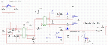
Everything is solder together on prototype board, and when i power it up current limiting is working, range is from 250 mA to 3A, but voltage control is not responding... i don't have feedback loop compensation for now. I will post pictures and schematic later today.

IR2110 refused to work with +18 VDC, so i lowered the voltage to +12 VDC and this is the results..(maybe i should raise voltage to +15 VDC) now i must add compensation, wind the coil with litz wire and solve the problem with voltage feedback loop.
 

KX36

New member
I don't know how you can tell your crude OCP (not CC) which you've added onto the feedback loop is working when the feedback loop isn't. There are multiple problems with your circuit. As it isn't sensing the inductor current like would be necessary for an actual CC feedback loop, you probably won't get the multiple switching transitions as I described. It will probably still oscillate around the current limit when it comes into action, which really isn't a good thing to design in if you plan to use it for anything other than fault protection. The current sense resistor will also cause a burden voltage error on the output voltage as it's outside the voltage loop.

I'll point out this though, look at what pins R17 is between and ask yourself how is that different from how opamps are usually.
 
Last edited:
Top