First smps

Silvio

Well-known member
Correction


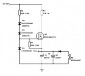
According to my schematic regarding the constant current source in 350w smps based on borysgo2 here is a better explanation so that you can better understand how it works.

1) Thermister limiting inrush current starts charging bulk caps. Now TR1 is biased via R1, ZD1 and ZD2 this will stabilize the voltage on the collector to 170v via R2
(R2 can be reduced to 33k)and also will drive the base of TR2 to 10v. As TR2 collector is in series with R2 current is limited to around 5mA This was enough to supply the IR 2153 chip however if more current is needed you can change the transistors like MJE340 and reduce the value of R2 to give more power to TR2. Now TR2 starts charging C3 until the trigger voltage for the SG3525 (8v) is reached however in my case it was 10uf and the reason for this was as the current limiter was shunting the supply rail to ground when it operates and this had to be done quickly discharging also C3 in the process. In your case you can add more capacitance here and more time will be added before trigger voltage is reached so you see at 170v will be enough and in the mean time C3 is charging, the bulk caps will continue as well and their voltage will rise near the peak before oscillation commences. However more capacitance in C3 gives more current at start up. You can always simulate it on LT SPICE and see the result

Regards

Silvio
 

brady

Member
I've been thinking on the circuit for a bit and came up with a startup circuit similar in nature that uses one less transistor (actually only one mosfet). It functions essentially the same. See the diagram below:
SMPS_startup.jpg

Essentially the mosfet will not be forward active until the rail voltage surpasses the sum of the zener voltage drops (334v). Once the mosfet is active, current will flow limited by R2 until the aux voltage reaches 14V - Vgs(th), so using the mosfet specified, it will charge up to a minimum of 10 volts and a maximum of 12 volts depending on the threshold voltage of the specific mosfet before the mosfet begins to current limit. Once the aux supply activates the aux supply voltage will rise and cause vgs to go negative, thus shutting off the startup supply. I have done several simulations of the circuit and it seems very robust.
 

Attachments

  • SMPS_startup.jpg
    SMPS_startup.jpg
    15.5 KB · Views: 24

brady

Member
Hi Brady, great effort here! My experience is high voltage SMPS have a nasty habit of blowing up under abnormal conditions so I do a bit of extra work to try and make them more robust.

I notice your current sensing is only in the tail of the lowside mosfet so there is nothing to prevent overstress of the high side mosfet nor core saturation during its conduction. I would normally use a current transformer in the primary circuit to ensure both half cycles are protected, this also helps to ensure flux balance and prevent center tap voltage wander.

Another related technique is to use a film capacitor in series between the center tap of the large capacitors and the primary, this has lots of effects nearly all beneficial, it limits the instantaneous s/c current, helps to swamp impedance mismatches between high and low side everything in the bridge and again helps to keep the ct voltage in the center of those large caps that are unlikely to have a high enough voltage rating to withstand rail to rail wander.

John

Thanks for the recognition! :cool:

It is my understanding that the two coupling capacitors on the half bridge will keep flux walking in check. I did some LT spice simulations to confirm this as well. I believe since it will be self balanced, measuring current from one side will be adequate for preventing overcurrent. This exact scenario is actually discussed in the reference book I am using and says that the capacitors will be enoughkeep the volt-seconds in balance, thus keeping the currents on both sides close to equal.

However, to be on the safe side, it is likely I am going to go with the film cap in series with the primary as you mentioned.

thanks,
Brady
 

Silvio

Well-known member
I've been thinking on the circuit for a bit and came up with a startup circuit similar in nature that uses one less transistor (actually only one mosfet). It functions essentially the same. See the diagram below:
View attachment 6024

Essentially the mosfet will not be forward active until the rail voltage surpasses the sum of the zener voltage drops (334v). Once the mosfet is active, current will flow limited by R2 until the aux voltage reaches 14V - Vgs(th), so using the mosfet specified, it will charge up to a minimum of 10 volts and a maximum of 12 volts depending on the threshold voltage of the specific mosfet before the mosfet begins to current limit. Once the aux supply activates the aux supply voltage will rise and cause vgs to go negative, thus shutting off the startup supply. I have done several simulations of the circuit and it seems very robust.

What is going to regulate your auxiliary supply? what about voltage fluctuations? I believe you are using an IR2110 after the SG3525 to drive your fets. Did you calculate what is the current needed to drive your fets in adequate time? I am saying this is because the auxiliary needs to supply all the current after switch on and somehow you have to be careful with the number of turns when winding it. You also have to keep in mind that if you are going to regulate your supply in the future hence if you regulate from the primary all voltages will fluctuate when varying the output. Here comes another consideration that either you make your startup robust enough to handle all the power needed even during normal operation. Or you must go for a separate power source. This may work for you take a look on the link below

http://www.ebay.co.uk/itm/SM-PLF12B...029608?hash=item4634a66068:g:rmEAAOSwe-FU2vF0

You can eliminate the soft start and the bulk cap on this small smps and feed it directly from your DC rail (380v) That is what I did with my 1000watt smps. The difference is that I found mine on an old Air conditioner PCB and took it off from there and adjusted it to suit my needs (just changing the zener to rise up the voltage from 12 to 15vdc @ 500mA) and you know what? Its got a built in 1/2 second delay after switch on when the output comes out and also short circuit protection. It sits vertically and around 3.5cm square in size. It was just tailor made for me Ha Ha!

Silvio
 

Silvio

Well-known member
I've been thinking on the circuit for a bit and came up with a startup circuit similar in nature that uses one less transistor (actually only one mosfet). It functions essentially the same. See the diagram below:
View attachment 6024

Essentially the mosfet will not be forward active until the rail voltage surpasses the sum of the zener voltage drops (334v). Once the mosfet is active, current will flow limited by R2 until the aux voltage reaches 14V - Vgs(th), so using the mosfet specified, it will charge up to a minimum of 10 volts and a maximum of 12 volts depending on the threshold voltage of the specific mosfet before the mosfet begins to current limit. Once the aux supply activates the aux supply voltage will rise and cause vgs to go negative, thus shutting off the startup supply. I have done several simulations of the circuit and it seems very robust.

What is going to regulate your auxiliary supply? what about voltage fluctuations? I believe you are using an IR2110 after the SG3525 to drive your fets. Did you calculate what is the current needed to drive your fets in adequate time? I am saying this is because the auxiliary needs to supply all the current after switch on and somehow you have to be careful with the number of turns when winding it. You also have to keep in mind that if you are going to regulate your supply in the future hence if you regulate from the primary all voltages will fluctuate when varying the output. Here comes another consideration that either you make your startup robust enough to handle all the power needed even during normal operation. Or you must go for a separate power source. This may work for you take a look on the link below

http://www.ebay.co.uk/itm/12V-400mA...944249?hash=item339e58af39:g:umoAAOSw6DtYSC4X

You can eliminate the soft start and the bulk cap on this small smps and feed it directly from your DC rail (380v) That is what I did with my 1000watt smps. The difference is that I found mine on an old Air conditioner PCB and took it off from there and adjusted it to suit my needs (just changing the zener to rise up the voltage from 12 to 15vdc @ 500mA) and you know what? Its got a built in 1/2 second delay after switch on when the output comes out and also short circuit protection. It sits vertically and around 3.5cm square in size. It was just tailor made for me Ha Ha!

Silvio
 
Last edited:

brady

Member
I'm actually thinking of using a LM7815 to regulate the auxilliary winding. I figure based on the MOSFET gate resistance plus an external gate resistance around 10 ohms, I should have drive peak current of 1A or so, which should handle just fine from the output capacitors after the regulator. With no gate resistor it can have a maximum peak current of 3.3A (limited by internal gate resistance).

Since the auxilliary will not be using an inductor, is it true that the output will not vary as much with duty cycle? It seems like no matter how short the pulse, the capacitors will still charge to the peak voltage if the current is available. That would effect the number of turns I need to do for the aux supply.

I was actually planning on attempting an optocoupler feedback at some point, although first priority is to get the supply functioning unregulated. I suppose if I can't get such feedback working, I can regulate from the aux supply or another winding.

I suppose I should order the controlling components and build up the circuit and do some testing how much current it is going to require before I decide on a startup supply. I am having trouble finding a transistor with enough gain to supply on the order of hundreds of milliamps. With just a normal transistor, it only can manage about 100-150mA.

I suppose if all else fails I can use an external supply like you used. I have seen many primitive low power supplies just like those that are available for purchase.

Regards,
Brady
 

fourtytwo

Leaving bad site ASAP!
I believe since it will be self balanced, measuring current from one side will be adequate for preventing overcurrent. This exact scenario is actually discussed in the reference book I am using and says that the capacitors will be enoughkeep the volt-seconds in balance, thus keeping the currents on both sides close to equal.Brady

Good you are familiar with LTspice, a very useful tool. Then I suggest you throw a short on the output just as the high side starts conducting and see what happens :) maybe your book doesn't entirely take account of the real world!

Good to know you are considering a film cap, I think you will find most if not all commercial designs use them, take apart a few there is much to learn, play close attention to transformer construction and attention to creepage and clearance, you might find a few tips for bias supply and inrush limiting too.

John
 

brady

Member
I did several tests in LT spice and determined that using two film caps vs. using one in series made no difference in performance. The transformer was self balancing. Note: the transformer is not directly tied to the center tap of the bulk capacitors in my design, only connected to the center of two film caps. If it were to be tied directly to the center tap of the bulk capacitors, the current balance would be very poor. However, with no significant performance differences, using a series capacitor makes logical sense for cost savings.

As far as the current balance, both currents typically stay very close to the same. there are occasionally some extreme mismatched pulses. Could you give some advice on turns for a current sense transformer and core selection? I don't have any knowledge in that area.

Thanks,
Brady
 

fourtytwo

Leaving bad site ASAP!
My first reply was lost so I hope this makes sense re-written from memory!

The major difference is in distribution of ripple currents and that is dependent upon ESR of all the components involved (including your bulks) so be sure to include ESR in your LTspice simulations or you will get completely erroneous results. I hope you have also included winding resistances and leakage inductance for your transformer and any other wound components.

You seem to be fixated on current balance during normal operation, I did suggest that you do some testing under extreme conditions i.e. output short circuit. Also LTspice is utopian, it doesn't take account of the real world such as mismatches in components and imperfections in transformer construction, it is unlikely that your model includes such things so be careful about making assumptions.

As for current transformers I am to lazy to wind hundreds of turns on a small ring core so buy them ready wound, 300-1000:1 in 5-50A are cheap! Simply thread the half bridge primary through the CT (single turn primary). The secondary is the rectified (by signal diodes) and connected to a load resistor to convert current into voltage e.g. if you want 100mV @ 10A using a 500:1 CT then R = 0.1/(10/500) = 5.
BTW everything in the current sensing path has to be as fast as possible including the control chip, no use putting op-amps in there you'll simply loose mosfets!

John
 

brady

Member
My first reply was lost so I hope this makes sense re-written from memory!

The major difference is in distribution of ripple currents and that is dependent upon ESR of all the components involved (including your bulks) so be sure to include ESR in your LTspice simulations or you will get completely erroneous results. I hope you have also included winding resistances and leakage inductance for your transformer and any other wound components.

You seem to be fixated on current balance during normal operation, I did suggest that you do some testing under extreme conditions i.e. output short circuit. Also LTspice is utopian, it doesn't take account of the real world such as mismatches in components and imperfections in transformer construction, it is unlikely that your model includes such things so be careful about making assumptions.

As for current transformers I am to lazy to wind hundreds of turns on a small ring core so buy them ready wound, 300-1000:1 in 5-50A are cheap! Simply thread the half bridge primary through the CT (single turn primary). The secondary is the rectified (by signal diodes) and connected to a load resistor to convert current into voltage e.g. if you want 100mV @ 10A using a 500:1 CT then R = 0.1/(10/500) = 5.
BTW everything in the current sensing path has to be as fast as possible including the control chip, no use putting op-amps in there you'll simply loose mosfets!

John

Using a sense resistor would have required an extra op amp for more gain, so looks like that is out of the question here without getting another dedicated controller with current limit! With a current sense transformer, rectifier, and load resistor, all that would be necessary is a fast comparator connected to the shutdown pin, correct?
 

fourtytwo

Leaving bad site ASAP!
Using a sense resistor would have required an extra op amp for more gain, so looks like that is out of the question here without getting another dedicated controller with current limit! With a current sense transformer, rectifier, and load resistor, all that would be necessary is a fast comparator connected to the shutdown pin, correct?

Yes exactly but you could just use a pot & no comparator to tune out the manufacturing range of the chips shutdown sense voltage. Of course what you really want is current mode controller in the first place like the UC2825/MC34025! This will dramatically improve your startup control, provide cycle by cycle protection to the mosfets, low startup current and UVLO built in. I use one of these with an IRS2110 driver in many direct offline designs, with of course a current transformer :)

Good luck
John
 

brady

Member
Okay, I have done a redesign taking all of the advice I have received into consideration. Please see the schematic and PCB layout below:

View attachment HalfBridgeSMPS.pdf


If there are no objections, I will be purchasing the parts.

I plan on getting the supply working open loop before I attempt to do a closed loop design. Hence why I placed headers on the power PCB, so that I can swap the controller boards easily without rebuilding the entire board. I also placed the driver chip closer to the mosfets as Silvio suggested. Please let me know.

Regards,
Brady
 

Attachments

  • HalfBridgePCB.pdf
    541.2 KB · Views: 58
Last edited:

brady

Member
Okay, I have done a redesign taking all of the advice I have received into consideration. Please see the schematic and PCB layout below:

View attachment 6025


If there are no objections, I will be purchasing the parts.

I plan on getting the supply working open loop before I attempt to do a closed loop design. Hence why I placed headers on the power PCB, so that I can swap the controller boards easily without rebuilding the entire board. I also placed the driver chip closer to the mosfets as Silvio suggested. Please let me know.

Regards,
Brady

Pleas ignore the PCB file in the previous post, use this file.
View attachment HalfBridgePCB.pdf
 

fourtytwo

Leaving bad site ASAP!
Have you worked out the delay time between an overcurrent and shutdown of the mosfets ? have you considered what effect this will have on the actual drain current at the time of turn off ? Why are you using a voltage mode control chip ? If you are happy you have answered all these questions to yourself then fine :)
 

brady

Member
The SG3525 has a built in shutdown propagation delay of 200 to 500ns. The comparator chip that I chose has a propagation delay of 80 to 150ns. I'm not sure if that will make a huge difference, but felt like having a digital input to the shutdown pin would be better than an analog signal. The goal is to perform pulse-by-pulse current limiting, which the SG3525 explicitly says is compatible with. I'm not really sure how to determine what current limit I will need to set in the first place, or determine what the drain current will be in such a condition.

Everything I've read has pointed to the half bridge topology being more compatible with voltage mode control. Current mode control can actually cause the flux balance to walk out faster. That's not to say it can't be done successfully, however. I just prefer to do my first supply without such complexities.

Regards,
Brady
 

fourtytwo

Leaving bad site ASAP!
Everything I've read has pointed to the half bridge topology being more compatible with voltage mode control. Current mode control can actually cause the flux balance to walk out faster. That's not to say it can't be done successfully, however. I just prefer to do my first supply without such complexities.
Regards,
Brady
There I have to agree with you, however I myself have failed to suffer this malaise in any noticeable way! I guess my transformers are conservative on flux density by allowing for a high mains that never happens in practice and the film capacitor prevents the CT of the bulks wavering hence they don't explode from overvoltage! Sure on the trafo side of the film cap there's a little wander but it never amounts to much and I guess even if the trafo saturates the cycle-cycle overcurrent prevents me loosing mosfets! Maybe I am just too damm lucky :)
John
 

brady

Member
Hello,

I have built up the power section and have been testing and wanted to give an update. After some testing I had a problem with the startup circuit short circuiting. I discovered this had to do with not having a base emitter resistor to bleed off parasitic charge. I also discovered the zener voltages were too great to permit adequate turn on. So, I made the following changes:

(1) Changed R5 from 50k to 33k
(2) Changed D1 from 160v zener to a 220k resistor (permits turn on at 170v instead of 330v).
(3) Added base-emitter resistor across Q4.

After these changes the startup circuit functioned properly and regulated to around 9.2 volts and powered the control circuit (I had this on a breadboard at the moment).

After I attempted to up the duty cycle on the control board I heard a pop sound. After some investigating I narrowed it down to a short on the power input for the IR2110. I cannot explain why it would have failed, however I did note that the auxilliary winding did not produce enough voltage to take over from the startup circuit, which was still runnning. From this I found I may need to change the auxilliary turns from 3 to 6 or 7 turns.

Currently I have no snubber on the primary. Should I place a temporary snubber or wait until I can make more measurements to determine the proper value?

Here are some images of the built up circuit and pcb (does not reflect changes mentioned above):

image1.JPG
image2.jpeg

Advice is appreciated!

Regards,
Brady
 

Silvio

Well-known member
Hello,

I have built up the power section and have been testing and wanted to give an update. After some testing I had a problem with the startup circuit short circuiting. I discovered this had to do with not having a base emitter resistor to bleed off parasitic charge. I also discovered the zener voltages were too great to permit adequate turn on. So, I made the following changes:

(1) Changed R5 from 50k to 33k
(2) Changed D1 from 160v zener to a 220k resistor (permits turn on at 170v instead of 330v).
(3) Added base-emitter resistor across Q4.

After these changes the startup circuit functioned properly and regulated to around 9.2 volts and powered the control circuit (I had this on a breadboard at the moment).

After I attempted to up the duty cycle on the control board I heard a pop sound. After some investigating I narrowed it down to a short on the power input for the IR2110. I cannot explain why it would have failed, however I did note that the auxilliary winding did not produce enough voltage to take over from the startup circuit, which was still runnning. From this I found I may need to change the auxilliary turns from 3 to 6 or 7 turns.

Currently I have no snubber on the primary. Should I place a temporary snubber or wait until I can make more measurements to determine the proper value?

Here are some images of the built up circuit and pcb (does not reflect changes mentioned above):

View attachment 6039
View attachment 6040

Advice is appreciated!

Regards,
Brady

Hi Brady I guess you ended up with the values that where on the schematic I told you to refer to in the beginning. These where experimented and tailored by Borysgo2. I was wondering why you wanted the bulk caps to charge to nearly the full voltage. One has to consider that as soon as it is loaded this voltage will quickly fall. I guess 160v zener will be ok in the start up. Regarding the auxiliary winding you will be better off selecting a voltage not less than 20volts on the lowest input mains voltage. The reason is that this voltage has to supply some current when needed at all times. You can then adjust the voltage with a series resistor according to demand of the smps . Head for 15 to 18volts supply never the less both sg3525 and ir2110 can take this voltage in the input. Allowing some voltage drop in the circuitry this will end up in the region of 12-13volts on the gates of the fets. I have been doing some tests on my SMPS today and that what I observed (around 3v-4v drop on the square wave output to the gates) My auxiliary supply is 14.5v loaded SMPS working and around 10 and 11 volts to the gates. The high side gate gets around 0.7volts less due to the diode feeding High side on IR2110.

As for the burn out of the IR2110 I cannot say anything yet, but I will ask you a few questions:- Did you hook up the scope at the low side gate to ground to see the wave form? Was your smps lightly loaded say 40watts or so. Did you hook a 150watt bulb on the fuse terminals instead of the fuse for protection. One last thing what is your volts per turn calculated in your trafo? is rectification of the aux supply (from Trafo) half wave or full.

DO NOT FORGET TO ISOLATE YOUR POWER SUPPLY (USE ISOLATION TRAFO OK?) Don't burn your scope

Silvio
 

brady

Member
I went ahead and increased the auxilliary to 7 turns (it is only half wave). I have the auxilliary regulated to 12 volts which will shut off the startup circuit since it regulates to around 9 volts.
I was not using a bulb for the fuse, i had a 5A ceramic slow-blow fuse installed. I am using an isolated variac to perform testing, which allows me to put in a range of voltages if necessary.

I didn't have a load on the output when the IC blew. Currently I actually don't know if the IC blew or if the mosfets did. I haven't removed them from the board, but I am measuing nearly a short across both mosfets and the input power to the IR2110 and almost all of its pins. The short scross the mosfets could be related to the IR2110 but I am not sure. I currently don't have any solder wick to remove the chip, so its just guessing.
 

brady

Member
Well, I just figured out why it failed.... Stupid me wired the High output from the IR2110 to the low side mosfet and the Low output to the high side mosfet on the PCB... Arghh!! Do you suppose I could just fix it with a jumper while I am still testing until I make the final PCB? I'm thinking both mosfets may be burned up at this point but perhaps the IR2110 survived? I'll have to check it out later.
 
Top