First smps

Silvio

Well-known member
Hi Brady, I did not design the over current circuit but copied it from Ludo 3232 schematic. All I know that it works well but it does not reset by itself. In your case you need a current limiter which will limit current according to your setting. This is going to be a bench supply so you will need it to work this way. Why not sense the dc output voltage instead and a 0.1 or 0.2 ohm resistor will do the job for you. it can either shut off the IR2110 or the SG3525 they both have a shut down pin. You can sense both outputs separately with 2 comparators thus having adjustable current sense for each side. you need an opto coupler here for isolation.

As for the diodes I used 1n4148 cheap and work well

Regards,
Silvio
 

brady

Member
Hi Brady, I did not design the over current circuit but copied it from Ludo 3232 schematic. All I know that it works well but it does not reset by itself. In your case you need a current limiter which will limit current according to your setting. This is going to be a bench supply so you will need it to work this way. Why not sense the dc output voltage instead and a 0.1 or 0.2 ohm resistor will do the job for you. it can either shut off the IR2110 or the SG3525 they both have a shut down pin. You can sense both outputs separately with 2 comparators thus having adjustable current sense for each side. you need an opto coupler here for isolation.

As for the diodes I used 1n4148 cheap and work well

Regards,
Silvio
I was planning to build a separate output stage to take care of the current and voltage regulation actually. I may attempt to do a buck stage on the output that is synchronized with the main supply clock. All I am concerned about for the main supply is preventing saturation and/or destroying the MOSFETs. Since the MOSFETs can handle 60A avalanche current I believe the transformer will likely saturate well before that point.

I added the current limiting comparator and measured the propagation delay time. It turns off the output of the SG3525 in only 180ns when the trip condition is reached. This is much better than the worst case listed on the datasheet fortunately. This number plus the delay of the IR2110 is how long it will have to turn of the fets after overcurrent is reached.

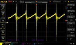
I made a measurement of my current waveform at the header X1. I changed the resistor across the current transformer secondary to 370 ohms and adjusted the output with the potentiometer after the rectifier. The only problem with the waveform that I can see is the ringing which may cause false triggering.

DS1Z_QuickPrint1.jpg
 

Silvio

Well-known member
Hi Brady, I have built a dual power supply using an ATX smps, This is just an idea that you could use. The ATX power supply was converted to be a variable one with a few changes on the TL494. It has variable voltage from 1volt up to the maximum of 30 volts. I rewind the trafo with a double output, After that I made a couple of linear regulators with current limiting. The atx follows the master linear regulator with around 4 volts more and I have little dissipation in the output transistor. The linear regulators are done with LM317t followed by TIP2955 and negative regulator is with LM337t and TIP3055. You can take a look at it on my Youtube channel there is an explanation and tests as well. there is even a look to the inside and explanation of what I done,

If you are interested I can post a basic schematic and show you what I done

LINK https://www.youtube.com/watch?v=uXzrmLrwPcg.

A buck converter will be good as well. Just see if it is worth building it or buy it ready made, plenty on e-bay

RINGING
Is that ringing coming from the sense resistor that you have on the source of the low side fet? What if you try to damp it with a small capacitor say 0.22 uf across the resistor and check your delay time again.

Another idea
You can sense the ripple current from the film capacitor (1Uf) in the middle of the bulk caps with a small 250p cap followed by a 10k in series resistor and going into the base of a small transistor. I guess pulling down the soft start pin to ground will limit your duty cycle and finally shutting down the sg chip. I am attaching a couple of diagrams so that you can take the idea. The full schematic is from Betchler smps to see how he is driving the soft start pin to limit current. The second one is from the 350w first smps I built to see the capacitive coupling to drive a small transistor. From the two you can combine a piece from both to create something that may work for you. Just breadboard it and try it out. This is my future idea when building a regulated supply and eliminating the current trafo.

Regards

Silvio
 

Attachments

  • Betchler smps 50v regulated.pdf
    389.9 KB · Views: 71
  • SMPS 350 watts.pdf
    2.3 MB · Views: 111

brady

Member
Hello,

I apologize for not getting back to you sooner. It's been busy.

I was actually planning on doing a buck+linear output similar to what you describe. I have to do it this way because there are two independent channels which prevents me from being able to adjust the output from the main supply.

There may have been a misunderstanding, because this supply uses a current transformer and not a sense resistor. I believe the ringing is coming from the primary not having a snubber at this point.

I have been trying to get the current limiting to work with an external comparator to do pulse-by-pulse shutdown. It actually seems to work pretty well, but for some reason it will randomly fail and both mosfets will fail (along with the IR2110 and in one case even the SG3525). I don't know if there is a flaw in the circuit or if it is my fault, because it did happen when I was changing the current limit setting on the comparator (increasing limit caused the mosfets to burn up as the bulbs turned on). I think the problem comes down to speed, and I am going to try connecting the current sense directly to the shutdown pin and adjust the current sense level for increased response time. That seems to be the quickest way to shut it down. From measurements I determined that it shuts down at 0.8 volts (due to the internal transistor base-emitter voltage) and further voltage causes the soft start capacitor to discharge, so a gross over current will reset the soft-start.

Another option I was going to try was swapping the SG3525 with a UC2825/MC34025 as suggested by fourtytwo since it has built in current limiting.

Regards,
Brady
 
Top