Heatsink Temperature

Paulo

New member
What's up guys? This is my first post and I'm sorry for my bad English.. I'm learning yet. My native language is Portuguese and English is so complicated for me. Please if anybody desire to correct something that I wrote wrong or give me tips to improve my words don't be shy, I'll stay too happy :)
I developed a single 12V 10A @40khz not regulated SMPS Half Bridge basically with IR2153, 2X IRF840, MUR1620CT and now it works ok :D I've tested it around a 12,2V X 11,1A for 8 hours long lot of times(more than 10) and everything it's ok, incredibly nothing (more lol) blow up :D The ambiente temperature is around 28ºC (83ºF). The 2XIRF840's heatsink maximum temperature is 50ºC(122ºF) and I think it's a good temperature. The MUR1620CT's heatsink maximum temperature (measured at 12mm [1/2Inch] of the MUR) is 85ºC (185ºF). Is it too hot? I really don't wanna change the MUR heatsink because there are not more space for it then I will improve a thermal shutdown with auto restart. The MUR1620CT maximum operating junction temperature is 175ºC and finally my question is: How many ºC (or ºF) should I program the shutdown?
Thank you all,
Paulo.
 

MicrosiM

Administrator
Staff member
I think best and safest temperature is 85C to 90C Maximum

Taking into account some calculation for heat transfer from die to the heat sink, etc...


Regards
 

KX36

New member
I agree with Microsim. It is important to remember there is a temperature difference from die to case to thermal pad to heatsink and it's the die temperature you want to protect. You can measure temperature of the package's tab but it's still not the die temperature.

Other than making a bigger heatsink, you could obviously add forced air cooling if it is passively cooled.

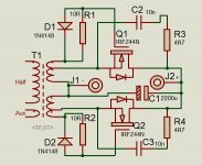
Another more complicated option is to change the schottky rectifier to a self-driven synchronous FET rectifier as your output voltage is coincidentally about right for a gate voltage, but it's probably not worth it. It's not as simple, self-driven isn't ideal and won't get the lowest dissipation a synchronous rectifier can do and may not be much less than the schottky. It's more for lower voltages and higher currents. You'd also probably have to redo the PCB. You'd have to do the calculations to see if it would be worthwhile. On the other hand, the IR2153 gives a close to ideal 50% duty cycle square wave output with quite fast edges so that quite well suits self driven synchronous rectification.

[I've just done a synchronous self driven synchronous rectifier and it gets to about 83'C on the tab with a 10A load passively cooled with a very small heatsink, although I think I have partially damaged one of the FETs. The nominal max load current is actually 7.5A so that's running over spec. This is only a prototype, the heatsink is a bit of scrap aluminium barely bigger than the pair of TO220s. Doing the calculations the difference in dissipation is about 5W with the schottkys, 1-2W with the FETs for mine.]
 
Last edited:

Paulo

New member
Thank you both! KX36 I'd really like to improve a synchronous rectification because I believe that we should do everything that we can to have a better performance on a SMPS. I'd tried but I don't had a satisfactory results, this is something beyond of my knowledge. Synchronous.jpg I had a tiny heatsink 1X2 inch, low temperature.. below 55ºC @ 12A, a little higher output voltage 12,2V => 13,0V, but.... a little bit of buzzing on first 1-2 minutes :x: after those minutes I think that I had a very good results. Basically this happened with the annex circuit and after a few changes too. Maybe a noise on a gate driver's secondary is what introduces a buzz. I tried a gate RC filter and had betters results but this introduces a delay on circuit and I can´t analyse this now, I need a oscilloscope to understand what is happened. With a fast diode, MUR1620CT, everything works ok except by the overheating. Yes, it's passively cooled. I don´t wanna a fan because I believe if I use a reserved place for it I can to put a bigger heatsink it will works ok, so bigger heatsink is a better choice :) A heatsink have lower cost too. If anybody can help me with synchronous rectification I really wanna know how it works. Yes, I really need some calculations too MicrosiM, I'll see this soon.
Best regards,
Paulo.
 
Last edited:

MicrosiM

Administrator
Staff member
Best and cheapest idea of synchronous rectifier is to drive 4 FETs (Full Bridge) at the output of the SMPS from a GDT, driven from the main PWM controller. in FIXED frequency mode.


Thats the best method I have seen, and almost cheapest.

Good luck
 
Top