Inductive Spike for Push-Pull car audio supply

maxpayne

New member
I am facing this problem, which is causing the two push-pull MOSFET to extreme stresses.

I am using this to power TAS5630 amp. the boost converter is converting the 12V DC voltage to 36V DC (unregulated). As this is a car amplifier so the battery voltage can be 10V to 14.5V.

Everything is ok upto 13.5V DC input. But when the input voltage is higher than that, inductive spike is seen at the MOSFET drain and they becomes hot.
At 13.8V or higher the kick exceeds the max Vds 40V and the FETs are starting to runaway.

I have attached some screenshot and unsnubbed oscillation at MOSFET drain. Please help me to remove the inductive kick @15V.
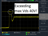
0drain-gnd1 @14.5V2.png

View attachment test waveform.zip
 

wally7856

New member
I think i see what is going on here. Your circuit is for the most part behaving normally. The leading edge spike is a manifestation of transformer parasitic's, leakage inductance and capacitance.

As a general rule you need a 50 vdc minimum rated mosfet for the switch. And 50 to 60vdc is the common range. 40vdc parts are known to burn out in automotive push pull power supplies.

I am not sure if you can wind your transformer in such a way to lower your leading edge spike enough for reliable operation.

One idea i have that might work is a much slower turn on. You have 3.9 ohm gate resistors, start with 30 ohms and see if the gate slow down decreases the spike. You can increase the gate resistor until the mosfet gets hot from to slow a turn on. You can probably go as high as 90 ohms or so, in your tests.

Let us know what happened if you do the tests.
 

maxpayne

New member
I think i see what is going on here. Your circuit is for the most part behaving normally. The leading edge spike is a manifestation of transformer parasitic's, leakage inductance and capacitance.

As a general rule you need a 50 vdc minimum rated mosfet for the switch. And 50 to 60vdc is the common range. 40vdc parts are known to burn out in automotive push pull power supplies.

I am not sure if you can wind your transformer in such a way to lower your leading edge spike enough for reliable operation.

One idea i have that might work is a much slower turn on. You have 3.9 ohm gate resistors, start with 30 ohms and see if the gate slow down decreases the spike. You can increase the gate resistor until the mosfet gets hot from to slow a turn on. You can probably go as high as 90 ohms or so, in your tests.

Let us know what happened if you do the tests.

Thanks. I will try to do so. :)
 

wally7856

New member
I saw your thread on diya, 3 pages, lots or arguing and no answers. But now that i have seen your transformer construction i know we can build it better.

Do you have the specs of your toroid, Ae or Ac (area of core), type of material, physical dimensions.
What wire are you using.
 

wally7856

New member
An inductive leakage spike gets higher with load current. A smps without an inductor has to work very hard, the primary must supply large slugs of current. Here is the calculations for your output inductor. Check your secondary with your scope to verify my conclusion of 63.52 Khz.

push pull with single winding secondary.

Secondary
300W
36vdc
8.3A

RT = 12K
CT = 1.8nF
18uS = 56khz from timing chart / 2 = switching frequency = 28Khz.
31.76 khz, from mosfet waveform = Actual switching frequency.
31.76 khz x 2 = secondary inductor frequency = 63.52 Khz

From pressmans book 3rd edition.
inductor calculation
Lo = 0.5VoT/Ion

Lo = Output inductor in henery's
.5 = constant
Vo = Output voltage = 36vdc
T = Time in seconds = 1/63.52Khz = 15.74 uS = 0.000,015,74 Seconds
Ion = I out nominal = 8.3A

.5 x 36vdc x 0.000,015,74 Seconds/ 8.3A = 34 uH, minimum.

The current rating of the inductor has to be oversized a minimum of 20%,

30% better = 8.3A x 1.3 = 10.8 A

My digikey search only showed two inductors in stock that met the requirements.

http://www.digikey.com/product-sear...1&stock=1&quantity=0&ptm=0&fid=0&pageSize=500
 

wally7856

New member
One correction, the frequency doubling from 31.76 Khz to 63.52 Khz is after the FWB rectifier not at the secondary winding. And the inductor goes in the circuit in the positive line after the FWB rectifier.

Also to reduce any spike a RC snubber on the secondary reflects back to the primary, but you can still keep your primary snubbers.

So to reduce the leading edge spike.
Try larger gate resistor.
Add output inductor.
Add RC to secondary winding. Fine tune with scope.
Rewind transformer, after you get me some specs.
 

maxpayne

New member
I saw your thread on diya, 3 pages, lots or arguing and no answers. But now that i have seen your transformer construction i know we can build it better.

Do you have the specs of your toroid, Ae or Ac (area of core), type of material, physical dimensions.
What wire are you using.


Thanks Wally7856 for your help. I really appreciate your seriousness on this ! :)

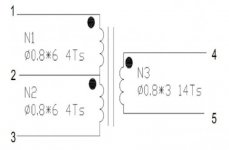
Here is the details of the transformer:

Core material: R5K
Turn Ratio: 4:4:12
Toroid Inner Diameter: 19.5mm
Toroid Outer Diamter: 27.7 mm
Toroid Height: 18.1 mm

I have also attached the transformer schem.
 

Attachments

  • schem.jpg
    schem.jpg
    16.3 KB · Views: 16

maxpayne

New member
An inductive leakage spike gets higher with load current. A smps without an inductor has to work very hard, the primary must supply large slugs of current. Here is the calculations for your output inductor. Check your secondary with your scope to verify my conclusion of 63.52 Khz.

push pull with single winding secondary.

Secondary
300W
36vdc
8.3A

RT = 12K
CT = 1.8nF
18uS = 56khz from timing chart / 2 = switching frequency = 28Khz.
31.76 khz, from mosfet waveform = Actual switching frequency.
31.76 khz x 2 = secondary inductor frequency = 63.52 Khz

From pressmans book 3rd edition.
inductor calculation
Lo = 0.5VoT/Ion

Lo = Output inductor in henery's
.5 = constant
Vo = Output voltage = 36vdc
T = Time in seconds = 1/63.52Khz = 15.74 uS = 0.000,015,74 Seconds
Ion = I out nominal = 8.3A

.5 x 36vdc x 0.000,015,74 Seconds/ 8.3A = 34 uH, minimum.

The current rating of the inductor has to be oversized a minimum of 20%,

30% better = 8.3A x 1.3 = 10.8 A

My digikey search only showed two inductors in stock that met the requirements.

http://www.digikey.com/product-sear...1&stock=1&quantity=0&ptm=0&fid=0&pageSize=500

I dont want to use output inductor for this application as this is unregulated supply. I have seen an existing amplifier bought from market which is working without any spike using just a capacitor secondary filter. So it is possible to achieve spike-less without secondary inductor. I am also planning to replace the transformer from that one to my design to see if the things improve.
 

maxpayne

New member
I have rewinded the trasnformer with evenly distributed winding. It seems performance is much better now as the spike is appearing just after 14.3V,

Previously at 14.3V the standby current was 1.2A
Now, after rewinding, at 14.3V standby current is .65A

I have hand wounded the trasnformer, Maybe I will get more performance if the toroid is machine wounded. But before that I will test it with the transformer from the market bought amp. :)
 

maxpayne

New member
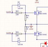
I used a gate drive resistor of 22R and added 1n4148 diode across the gate drive resistor so that turn on is slow and turn off is fast. Now performance is improved and the wavehspae is clean till 14.6V. After that the spike is again starting to appear.

Is there anything I can do with the snubber network ? How can I calculate the resistor and capacitor value of the network ? I am following AN11160 application note from NXP.
 

maxpayne

New member
This is the best ap note for snubbers.

https://www.maximintegrated.com/en/app-notes/index.mvp/id/3835

How did adding the 1n4148 affect the spike. Did you try bigger resistors than 22 ohm.

I tried that Maxim note also. But didnt get satisfactory result than with 10R and 15nF cap.

Attached is the modified gate drive circuit.
During positive half cycle gate will get the pulse via 22R resistor. During negative half cycle or turnoff, the diode will be forward biased causing the gate capacitor quickly discharged.
modified gate drive.jpg
 

wally7856

New member
I looked at those transformer / toroid specs. You are running about 4000 Gauss. You should be closer to 1600 Gauss. This transformer will get HOT under load.

If you are interested in re-designing the transformer, change operating frequency, possibly change wire. let me know. It is a lot of work to come up with a good design, i will not do it if you are ok with what you have.
 

maxpayne

New member
I looked at those transformer / toroid specs. You are running about 4000 Gauss. You should be closer to 1600 Gauss. This transformer will get HOT under load.

If you are interested in re-designing the transformer, change operating frequency, possibly change wire. let me know. It is a lot of work to come up with a good design, i will not do it if you are ok with what you have.

Wally7856, I really appreciate your help in this regard.

I will love to design an optimum transformer with your help. Presently I am following http://www.bcae1.com/trnsfrmr.htm for designing it. But I would like to know the step by step procedure. :)
 

wally7856

New member
You are fighting leakage inductance, the coupling of the primary and secondary windings. So one primary and one secondary on top of each other the same width is OK. But a sandwiched primary with a secondary on both sides the same width is better, or sec-pri sec, as good as you can get.

In your case it is harder because of the push pull = two primarys. So the best you can do is split your secondary to 7 turns + 7 turns and for the primary in the middle you take your primary wires lets say 6 wires and alternate them pri 1 and pri 2, So you would wind a total of 12 wires 4 turns, and the 12 wires would alternate pri 1 pri 2.

When you are done you have to connect the 2 primarys so the phase is correct. You have a red start and a green start that is the dot in the schematic, that is were you start winding. when you are done you have to wire it so that the 2 windings are in series. Look at the dot end as + so the first winding is +-, connected to the second winding +-, if these were 1.5v batterys you would get 3v.

The secondarys must be connected in series also so they add up or you will get zero volts out.

So you have sec-pri-sec, wound on your toroid.
 

wally7856

New member
The calculator in that link you provided works well, try these numbers.

14.8vdc, 70,000 hz, 1800 Gauss, Ae Core Area .74 = 4 turns

70,000 hz is the transformer switching frequency. So the controller must run at 2x that frequency or 140 Khz. Notice i worked it out so you have the same number of turns. The only difference is that you have higher frequency and lower more realistic Gauss.

You can actually change your RC time constant on your power supply now and try this and see how it affects your circuit. You may have to re-do your snubbers. Also now if you want to add an output inductor it will be much smaller because of the higher frequency.


inductor calculation
Lo = 0.5VoT/Ion

Lo = Output inductor in Henery's
.5 = constant
Vo = Output voltage = 36vdc
T = Time in seconds = 140 Khz = 7.14 uS = 0.000,007,14 Seconds
Ion = I out nominal = 8.3A

.5 x 36vdc x 0.000,007,14 Seconds / 8.3A = 15.5 uH, minimum.

The current rating of the inductor has to be over-sized a minimum of 20%,

30% better = 8.3A x 1.3 = 10.8 A

These are fairly small approximately .7" x .7", 17 mm x 17 mm, $3.5 usd


http://www.digikey.com/product-sear...1&stock=1&quantity=0&ptm=0&fid=0&pageSize=500
 

wally7856

New member
If you rewind your transformer try this.
3 layers, Sec-Pri-Sec

1st layer, 7 turns, 4 strands of .8mm, evenly spaced around toroid.

2nd layer, 4 turns, 14 strands of .8mm, evenly spaced around toroid.
(two primarys, 7 turns each, alternating strands)

3rd layer, 7 turns, 4 strands of .8mm, evenly spaced around toroid.

This is easy for me to say, hard for you to do. 4 strands are not to hard.

But 14 strands will require two men and a boy to wind them.
 

maxpayne

New member
The calculator in that link you provided works well, try these numbers.

14.8vdc, 70,000 hz, 1800 Gauss, Ae Core Area .74 = 4 turns

70,000 hz is the transformer switching frequency. So the controller must run at 2x that frequency or 140 Khz. Notice i worked it out so you have the same number of turns. The only difference is that you have higher frequency and lower more realistic Gauss.

You can actually change your RC time constant on your power supply now and try this and see how it affects your circuit. You may have to re-do your snubbers. Also now if you want to add an output inductor it will be much smaller because of the higher frequency.


inductor calculation
Lo = 0.5VoT/Ion

Lo = Output inductor in Henery's
.5 = constant
Vo = Output voltage = 36vdc
T = Time in seconds = 140 Khz = 7.14 uS = 0.000,007,14 Seconds
Ion = I out nominal = 8.3A

.5 x 36vdc x 0.000,007,14 Seconds / 8.3A = 15.5 uH, minimum.

The current rating of the inductor has to be over-sized a minimum of 20%,

30% better = 8.3A x 1.3 = 10.8 A

These are fairly small approximately .7" x .7", 17 mm x 17 mm, $3.5 usd


http://www.digikey.com/product-sear...1&stock=1&quantity=0&ptm=0&fid=0&pageSize=500

I see you have increased the switching frequency very high ! Would not it increase the conduction loss of the MOSFET ? In the site www.bcae1.com, the author mentioned that car audio booster normally use switching frequency less than 35KHz (Don't know though why is that )
 
Top