Hi everyone,
I'm building a push pull converter, and my MOSFETs aren't switching properly when given the signal to. I'm assuming that it's some kind of snubber problem, but I don't know. Maybe a TVS diode would help?
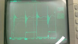
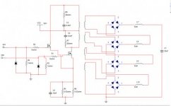
The circuit is attached; the MOSFETS are IXFX30N100Q2 and they are being given a signal from a MC34152P driver chip. I've also attached a photo of the waveforms without the RC snubber across the transformer coils to Vin; I appear to have not taken with the snubber (i.e. the 6,8nF cap, and the 80R resistor), but the sharp peak was exactly the same, but the oscillation before the circuit goes high again was reduced in frequency. The trasnformer is one big transformer; all the secondary coils are the same, ad the job of the circuit is to charge the capacitor to 3500V volts, which is why I've done it with a split secondary like that.
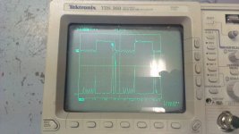
In the scope picture, channel one is the input to the MOSFET gate, channel 2 is the drain voltage. I was expecting them to be almost opposing square waves, but this is clearly not the case. Can anyone offer any suggestions?
Oh, and although the diagram shows a 50V input, as does the scope, it will need be running off of mains, i.e. 320V; at the moment I have it connected to a variac.
It so nearly works, but not quite! Any help would really be appreciated.
I'm building a push pull converter, and my MOSFETs aren't switching properly when given the signal to. I'm assuming that it's some kind of snubber problem, but I don't know. Maybe a TVS diode would help?
The circuit is attached; the MOSFETS are IXFX30N100Q2 and they are being given a signal from a MC34152P driver chip. I've also attached a photo of the waveforms without the RC snubber across the transformer coils to Vin; I appear to have not taken with the snubber (i.e. the 6,8nF cap, and the 80R resistor), but the sharp peak was exactly the same, but the oscillation before the circuit goes high again was reduced in frequency. The trasnformer is one big transformer; all the secondary coils are the same, ad the job of the circuit is to charge the capacitor to 3500V volts, which is why I've done it with a split secondary like that.
In the scope picture, channel one is the input to the MOSFET gate, channel 2 is the drain voltage. I was expecting them to be almost opposing square waves, but this is clearly not the case. Can anyone offer any suggestions?
Oh, and although the diagram shows a 50V input, as does the scope, it will need be running off of mains, i.e. 320V; at the moment I have it connected to a variac.
It so nearly works, but not quite! Any help would really be appreciated.
Attachments
-
 Switch ringing.jpg280.1 KB · Views: 51
 -
 Switching.jpg19 KB · Views: 97