obiwan
New member
For a very specific application, a 100V @ 10 A power supply is needed.
As galvanic isolation is not a requirement and 400V DC is available at the final destination location.
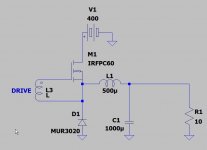
My first experiment was to build a buck converter. I calculated the filter, made a ring core inductor.
I used an old proven pulse drive board for the high side MOSFET with transformer coupling.
The switching frequency is 60 KHz , I started with a 25% duty cycle, 4uS on / 12us off, and the prototype worked fine up to 2A load with a single IRFPC60 MOSFET.
I didn't closed the loop, used just a Variac to adjust the 0 to 400 VDC input to the switcher. The idea was to do some measurements first.
I used a big heatsink with a blower, and the case temperature measured was 26 degrees Celsius when outputted 100V @ 2A load.
The MOSFET, an IRFPC60 is rated 600V, 16A , 0.4 Ohm RDS(on).
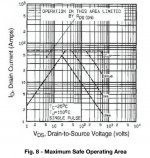
I have problems to understand SOA, because the MOSFET could stand a little more than 2A output current before blowing.


The SOA curve shows a maximum of 10us single pulse, while I'm using a 4us Ton pulse.
If this duty cycle of 4us with 400V and 2A current is pushing me out of the SOA, then how many parallel MOSFET's should I use ?
What am I doing wrong ?
As galvanic isolation is not a requirement and 400V DC is available at the final destination location.
My first experiment was to build a buck converter. I calculated the filter, made a ring core inductor.
I used an old proven pulse drive board for the high side MOSFET with transformer coupling.
The switching frequency is 60 KHz , I started with a 25% duty cycle, 4uS on / 12us off, and the prototype worked fine up to 2A load with a single IRFPC60 MOSFET.
I didn't closed the loop, used just a Variac to adjust the 0 to 400 VDC input to the switcher. The idea was to do some measurements first.
I used a big heatsink with a blower, and the case temperature measured was 26 degrees Celsius when outputted 100V @ 2A load.
The MOSFET, an IRFPC60 is rated 600V, 16A , 0.4 Ohm RDS(on).
I have problems to understand SOA, because the MOSFET could stand a little more than 2A output current before blowing.


The SOA curve shows a maximum of 10us single pulse, while I'm using a 4us Ton pulse.
If this duty cycle of 4us with 400V and 2A current is pushing me out of the SOA, then how many parallel MOSFET's should I use ?
What am I doing wrong ?
