On resistance of MOSFETs vs temperature

lucas-nld

New member
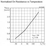
I'm in the process of doing the calculations for a 1kw half bridge SMPS, and as part of that I wanted to calculate the estimated maximum dissipation in the MOSFETs, so I can decide which MOSFETs I need and which cooling fins to put on them. Pretty much every MOSFET mentions their typical Rds on the first page, and in my case I was looking to use a pair of IRFP460's and wanted to do the calculations based on them (their typical Rds is 0R22). But when I read the rest of ST's datasheet for their IRFP460, I saw a graph that lists the Rds versus the junction temperature. However, the graph mentions that at room temperature the Rds would be 1R0, and it would take a temperature of about -100C for the Rds to be about 0R20, which is completely unpractical in real life. I'm only assuming that the low "typical" Rds resistances mentioned on the first page of the datasheet and in the description of MOSFETs at electronic component distributors is nothing but a sales trick, but under real life conditions they all have a much higher Rds than what is listed as their "typical" Rds. Is there anyone who can tell me that with certainty, or which Rds I should look for? I've added an image of the Rds vs Tj graph from ST's IRFP460 datasheet for reference. IRFP460 Rds vs Tj.png
 

lucas-nld

New member
What I forgot to add (it seems as if I can't edit my previous post, for some reason?!), might the gate voltage be the reason for the different Rds on resistances? I know that the gate voltage is very important for the on resistance of a MOSFET, the higher the gate voltage, the lower the on resistance. And the gate voltage for the IRFP460 MOSFET from the table above was 10V, so might that be the reason why it has a much higher on resistance at room temperature, compared to it's listed "typical" resistance of ~0R22??
 

Silvio

Well-known member
Hi Lucas, I am also building an smps with IRFP 460 and your question caught my taught as well. It seems that it always is that way regarding RDS 0n versus temperature, I seen also the data sheet of the IRF740 and it is the same thing that RDS On rises with temperature. Well this brings out the fact that Keeping mosfets the cooler the better.

Regards
 

Luca

New member
Good evening Silvio and lucas, i've a suggestion for you, watch carefully that graph and you can notice that rappresent the Rds "normalized"....
Bye and have a nice.. SMPS ;)
 

Silvio

Well-known member
Hi Luca, thanks for the comment but I still do not understand what is the actual meaning of normalized in the graph. Can you please explain more in detail?
 

Luca

New member
Rdson normalized means that the value of the axis Y which is the multiplier to apply to the Rdson dependently from X-axis, the temperature.
For IRFP460 MOSFET this means that at about 23°C, the multiplier is 1 (y-axis), so that the final Rdson will be (1 x nominal value), which means 1 x 0.27 = 0.27 ohms.
For example, at about 70°C, the multiplier is 1.5, then Rdson will be 1.5 x 0.27 = 0.4 ohms.
An important thing to notice is that the nominal value of 0.27 ohms are declared with the same Vgs voltage of 10V, and this is not always true in a mosfet datasheet ...
Tipically 23°C can be assumed like "room temperature" and, last but not least, the graph is about Tj = T Junction of the power FET, this means inside the mosfet...
I hope this can help with the concept of Rdson, regards
Luca
 
Last edited:

Silvio

Well-known member
Rdson normalized means that the value of the axis Y which is the multiplier to apply to the Rdson dependently from X-axis, the temperature.
For IRFP460 MOSFET this means that at about 23°C, the multiplier is 1 (y-axis), so that the final Rdson will be (1 x nominal value), which means 1 x 0.27 = 0.27 ohms.
For example, at about 70°C, the multiplier is 1.5, then Rdson will be 1.5 x 0.27 = 0.4 ohms.
An important thing to notice is that the nominal value of 0.27 ohms are declared with the same Vgs voltage of 10V, and this is not always true in a mosfet datasheet ...
Tipically 23°C can be assumed like "room temperature" and, last but not least, the graph is about Tj = T Junction of the power FET, this means inside the mosfet...
I hope this can help with the concept of Rdson, regards
Luca

Thanks very much Luca, that was a very good explanation and I understood it well. I hope Lucas-nid read it as well. Well It happened that I have finished my 1000 watt smps and I also uploaded a video on the load test. I also posted the PDF file for it here. I got very good results with efficiency reaching 97% at the designed load (800 watts) however this goes down to around 95% at a 1100 watts. I used a cpu heat sink with a fitted 3 mm copper sheet to aid dissipation for the fets and diodes. I guess it is an overkill as working with the fan on at a 1000 watts the heat sink temperature hardly reaches 30 deg Celsius with an ambient temperature of 15 degrees. The copper wire is not designed to take full load continuous as it was designed for audio purposes and was calculated at 6 amps per square mm. Getting back to RDS on I guess one has to allow around 15 degrees more than the heat sink temperature to roughly calculate the junction temperature, considering having mica insulators in between and heatsink compound provided the fets and diodes are tightened well and also having a smooth flat surface to sit on.

Regards,

Silvio
 

Luca

New member
1.1kW of output power is 10% above the maximum that you expected... by the way reach the maximum efficiency it's not an easy challenge in SMPS.
The main key is about the converter topology, for 1kW i think is still ok an hard switching application but you can really consider a ZVS configuration, it help for EMI and EMC and really the efficiency could be 2% to 3% better than an hard switching topology. Of course ZVS configuration it's a little bit "complicated".
In your design, that i don't know what kind of topology are you using, for better efficciency you can reduce the RDson of the power FETs at the primary and/or try to drive it "stronger" but without compromise too much the dv/dt of Vds of them because in that case the FETs will blow... it's also important how fast you drive the gate and at which frequency.
Another really important role is about the output recfier diode, you can try to use better diode with less forward voltage drop and recovery time or replace it with power FETs with sincronous rectification tecnique.
For the primary mosfet you can try IPW60R07C6 from Infineon that have about 0.1 ohms for Rdson (1/2 of IRFP460) and slightly better total gate charge, 170nC instead 210nC, and also have 600V for max Vds that means you can run with much safety margin.
For power transformer, at 1kW, 6A per square mm it's still ok also for continuos work (with fan), if you have space for windings try to calculate for 5A per square mm that can help you a little with efficiency. The main key for transformer winding it's the high frequency impedance, so also for 1kW it's mandatory to use a good litz wire, like for all magnetics parts in a good SMPS.
 

Silvio

Well-known member
Hi Luca, as you may have not noticed I am new to smps and I built my smps on Ludo 3232 schematics. The layout is somewhat different as I wanted the pcb to be narrower but longer as this will fit better in an amplifier case. You can take a look if you like I posted the pdf file to share it with everyone. The pcb was designed by myself using Microsoft publisher and my brain to figure out how am I to pass with the traces and used a lot of common sense with the best of my knowledge.
In fact I used Litz wire in my smps. I made some reserch on how to fabricate it and got a few good tips in doing so. One drawback on Litz wire is that it tends to be more bulkier in size compared to normal copper, but I know that copper loses are far smaller than using normal solid enameled copper wire. My Litz wire is made of 0.16mm ecw. With all this in mind I tried to fit each winding in one layer enhancing better coupling hence better efficiency. The SMPS is intended for audio application.
I also posted a video showing my load test and I got around 96% efficiency at 800 watts this falling a little at 1100 watts. I had the meters compared before doing this test and I was sure that I did not get any false readings. If there was any the error margin is small. I measured the input current and voltage also the output current and voltage at the same time and took readings. I don't really know what to expect from an smps but that is the efficiency I got. The video I posted shows it all. Regarding EMI I think it is a bit more noisy than the smaller smps I built before this one which was a 350 rms one. About this issue I still have to see the effect when powering the amplifier.

Info Topology Half bridge. B max 1400 gauss at maximum input voltage. Frequency 65 Khz, Output voltage 80-0-80 at rated input voltage this rising to around 96volts at maximum voltage, the amplifier can take 100 volts per rail


Link to get you to My smps schematics and video http://www.diysmps.com/forums/showthread.php?872-1000w-smps-based-on-LUDO3232/page2

Thanks and regards

Silvio
 

lucas-nld

New member
Thank you for your reply, it is very clear and useful information you provided! I'm now planning on using STP28NM50N FETs in my half bridge converter, which have an on resistance of 0R135, giving me a dissipation of just 8,3W per MOSFET at maximum power. I'm going to use an ETD39 with 3C95 ferrite, running at 400KHz and wound with copper tape for both the primary and secundary windings. I know it will be a big challenge, because at such fast switching speeds everything needs to be designed very well, or else it will work poorly or even fail catastrophically. But I'm willing to accept the challenge in orde to make a very powerful yet compact regulated PSU, with both constant voltage and current regulation. I plan to eventually combine it with a microcontroller with dual DAC's, so I can set a specific output voltage and current by way of the microcontroller, giving me a lab powersupply with an output of 50V at 20A, regulated hopefully in increments of 10-20mV and 1-2mA. Such tight regulation might all be too much to ask so I won't mind if it would turn out to be a lot less tight then planned, but the SMPS itself is certainly the most important part, and when my parts arrive in the mail I will start with the project and post every step here on the forum, so thanks for making that possible by providing me with the much needed information!
 
Top