Push Pull Output Power Question

Digibin

New member
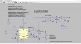
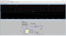
I'm designing an offline (230V) push pull converter to produce ~32V at 6A. I'm using the LT3721-1 controller and I have a simulation running in LTSpice. I don't have much experience with power electronics so I'm hoping someone here may be able to help with a lack of understanding. My issue is that under full load the output voltage does not regulate, instead it sags at around 28V. The duty cycle is at maximum - the converter cannot supply enough power. I'm not sure where the bottle neck is in terms of power throughput. Leading edge blanking is set to about 200ns (transformer current spikes measured at about 110ns). The current sense resistor is set low enough that the cycle by cycle current limiting does not occur, and that the duty cycle is at maximum under full load.

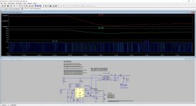
The reference for the voltage feedback error amplifier is 1.2V - and the voltage on the feedback pin is low at around 1.1V. The controller is trying to increase output power through maximum duty cycle but there is bottle neck somewhere.

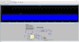
The transformer currents are greatest during startup and drop back during steady state. So the transformer is capable of more power throughput. The inductance values are based on 100:10 turns ratio on the Ferroxcube ETD49/25/16-3C90 core.

Where is the problem?

Circuit schematic attached.
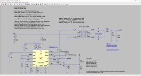
 

Attachments

  • LTC3721-1 Push Pull Converter.jpg
    LTC3721-1 Push Pull Converter.jpg
    19.6 KB · Views: 48
  • LTC3721-1 Push Pull Controller.zip
    182.2 KB · Views: 23

Digibin

New member
Must have converted to a jpg when uploading - it's a PNG on my machine. Hopefully this one is the correct size.
 

Attachments

  • LTC3721-1 Push Pull Converter.jpg
    LTC3721-1 Push Pull Converter.jpg
    322 KB · Views: 35

wally7856

New member
Looks good now.

The first thing i would look at is the primary voltage with a scope, is is dropping off. If not then it can only be the transformer or output capacitor. Is the output of the secondary a reasonable square wave, as in flat topped or does it have a big slope.

Give construction details of the transformer. How many winding's of each primary and secondary and what wire was used.
 

Digibin

New member
This is only in simulation at this point - I've not actually built the circuit. So the transformer is not built either, it is simply a 10:1 turns ratio with no flux saturation. I intend to do 100 primary turns and 10 secondary turns which will produce the inductance values shown on my schematic (based on the core mentioned in the first post). The supply voltage is a perfect 400V source so nothing wrong there.

How would the output capacitor have any affect on power throughput? I increased it to 1000uF just to check and the result is identical (same output voltage ~28V).

The secondary voltage waveforms are nice and square, albeit with some ripple on top. Picture attached.

Perhaps there is a quirk with the simulation, in which case I may be asking on the wrong forum.
 

Attachments

  • Secondary Waveforms.jpg
    Secondary Waveforms.jpg
    335.1 KB · Views: 11

wally7856

New member
If the capacitor value was to low the DC voltage should drop. The capacitor has to fill in the high ripple voltage.

I think your transformer has way to many turns on it l will get back to you in a little while on it.
 

wally7856

New member
With your current 100 pri turns you have 474 Gauss (.0474 Tesla) of flux, way to low. Rule of thumb go for 1600 Gauss. This would give you primary turns of 30 and secondary of 3 turns. Keeping your 10-1 ratio.
 

Digibin

New member
How did you calculate that?

I calculated 24mT of flux according to an equation in the Power Supply Cookbook (Marty Brown):

Bmax = E / (k*N*Ac*f) = 410 / (4*100*0.000211*200kHz) = 24mT

According to my calculations reducing the primary windings to 30 reduces the primary inductance to 3.78mH and the secondary inductance to 37.8uH. Simulating with these values, the output is unstable - it initially regulates to about 36V and after a few ms it drops, falls back to regulation at 36V and drops again some ms later, and so on. Wierd.

However, you made me realise that the inductances I calculated should be halved for the two primary windings either side of the centre tap. And also for the secondaries. Doing this the output does regulate at 32V, but also drops off and re-regulates in the same way as above (oscillation?). Waveform images attached.

It appears to drop out because the controller starts to apply minimal gate drive periods to the MOSFETS. The feedback voltage is steady at 1.2V so I'm not sure why the controller would drop the duty cycle so drastically. Current limiting is not occurring. Any ideas why the controller is failing to regulate?
 

Attachments

  • Waveforms1.jpg
    Waveforms1.jpg
    281.1 KB · Views: 8
  • Waveforms2.jpg
    Waveforms2.jpg
    323.8 KB · Views: 9

wally7856

New member
Your flux answer is wrong because you used 200khz oscillator frequency, not 100khz transformer frequency. Also either the Ae is off a few decades or your Vprim is missing a constant. And your schematic shows 400 V not 410 V.

Flux = Vpri 10^8 / 4 x freq x turns x Ae
40,000,000,000 /4 x 100,000 hz x 100 turns x 2.11 Ae cm^2 = 474 Gauss


turns = Vpri 10^8 / 4 x freq x Flux x Ae cm^2
40,000,000,000 / 4 x 100,000 hz x 1600 G, 2.11 Ae cm^2 = 29.6 turns


400volts/30turns = 13.33v/t

32v/13.33v= 2.4 turns, need 3 turns minimum.

3 turns x 13.333v = 40v


ETD49 3C90
Al = 4200 nH

L in mH = Al x N^2 / 1,000,000

L in mH = 4200 nH x 30^2 / 1,000,000 = 3.78 mH, each primary.

L in mH = 4200 nH x 3^2 / 1,000,000 = .0378 mH, each secondary.


Your simulations did not use 3.78 and .0378 mH
 

Digibin

New member
Your flux answer is wrong because you used 200khz oscillator frequency, not 100khz transformer frequency. Also either the Ae is off a few decades or your Vprim is missing a constant. And your schematic shows 400 V not 410 V.

Good point - the flux is indeed reversing direction at half the frequency of the push-pull oscillator frequency, thanks for pointing this out. The Ae core cross sectional area I took from the datasheet as 211mm^2 which translates to 0.000211m^2. The equation I'm using requires Ae in m^2 and no scaling constant on Vprim. I used 410V because this is the maximum voltage expected on the primary (400V +- 10V), and this would result in the greatest flux density. Correcting the frequency I now get the same results as you.

I did simulate with these values but the output was unstable, in the same way as shown in my earlier post. I've re-simulated now and attached waveforms of the output voltage. It's unstable and I'm not sure why. The oscillator is running continuously and the soft start timing capacitor is always fully charged so it's not shutting down due to overcurrent conditions (and nor should it - it's well under the threshold set). The dropouts occur when the controller starts to apply very short on periods to the MOSFET gates. But only sporadically - it will apply one or two short pulses then return to maximum duty cycle for a while. Almost like it's trying to regulate by dropping the duty cycle, but doing so far too much, causing the output to drop out? The compensation capacitor and feedback resistor are set to reject frequencies above 1kHz - is this low enough? It's 200x less than the switching frequency!
 

Attachments

  • Waveform1.jpg
    Waveform1.jpg
    309.3 KB · Views: 7
  • Waveform2.jpg
    Waveform2.jpg
    349 KB · Views: 8

Digibin

New member
I think the slope compensation may be causing the oscillation - is this output waveform characteristic of an unstable current control loop?

If I increase the slope compensation setting resistor on the current sense pin (R5 in my schematic) the output becomes more stable. At 800R the oscillations cease and the output is regulated to within 30V-32V.
 
Top