You are using an out of date browser. It may not display this or other websites correctly.
You should upgrade or use an alternative browser.
You should upgrade or use an alternative browser.
SG3252 SMPS 525W Problem with output power
- Thread starter Tomek
- Start date
Hi Silvio
I am after the first attempts to wind the transformer according to your description. I did not go perfect, I did not have a 4mm wide strip (I already bought).
Transformer Pictures:


2/2 primary winding


after the unwinding of the primary winding 2/2


2/2 secondary winding


1/2 secondary winding

1/2 primary winding

During the tests it turned out that the oscillations on the transistors almost disappeared (and without snubbers), but the transformer achieved much worse results than the previous one, with 5A core started to squeak.
I tried to solve the problem by adding a feedback but without isolation. I connected the primary ground to the secondary ground and the output from the voltage divider was soldered second to the pin no. 1 SG3525.
Feedback has started to work, but the load on the output was not possible. There were terrible oscillations on the transistors (Drain Source)
The whole was still powered from the autotransformer. I tried to connect the inverters in series with a 75W bulb. The effect was that the light bulb was constantly on or off, although the transformer was no longer squealing. On the second inverter's inactivation, the upper transistor was destroyed.
I have a dilemma where to look for a problem now, whether the transformer is guilty or something else. Maybe it was not professionally wound up, but the direction of the windings seems to me to have been preserved.
I am after the first attempts to wind the transformer according to your description. I did not go perfect, I did not have a 4mm wide strip (I already bought).
Transformer Pictures:
2/2 primary winding
after the unwinding of the primary winding 2/2
2/2 secondary winding
1/2 secondary winding
1/2 primary winding
During the tests it turned out that the oscillations on the transistors almost disappeared (and without snubbers), but the transformer achieved much worse results than the previous one, with 5A core started to squeak.
I tried to solve the problem by adding a feedback but without isolation. I connected the primary ground to the secondary ground and the output from the voltage divider was soldered second to the pin no. 1 SG3525.
Feedback has started to work, but the load on the output was not possible. There were terrible oscillations on the transistors (Drain Source)
The whole was still powered from the autotransformer. I tried to connect the inverters in series with a 75W bulb. The effect was that the light bulb was constantly on or off, although the transformer was no longer squealing. On the second inverter's inactivation, the upper transistor was destroyed.
I have a dilemma where to look for a problem now, whether the transformer is guilty or something else. Maybe it was not professionally wound up, but the direction of the windings seems to me to have been preserved.
Silvio
Well-known member
Hello Tomek, I see that you nearly got your transformer right but I could not see any sleeve in the secondary windings. I also noticed that the secondary windings where shifted to one side of the bobin and not centered well. I guess its due to not using a little margin tape to help you out in this problem.
Margin tape can be easily made from a wider piece of tape and by fixing it on a smooth clean surface and cut strips of it to the desired width. You can use a piece of masking tape for margin and then cover over it with maylar tape. firstly fix tape on top of each other (Masking tape and maylar tape) then cut them together with a ruler and scalpel or sharp blade. Use a piece of plastic pipe to wind the pieces of margin tape on it and put the pieces side by side on the pipe to get them ready to be used when winding the trafo.
feed back
do not use feed back yet until you can load the transformer successfully without getting those squeaks.
Try to monitor what is happening during the transformer is squeaking (see wave form with oscilloscope) If it comes distorted see if its coming from the gate as this could be reflected on the output.
It could be your pcb design is not good and high current paths are distorting the wave form by inducing noise on the low current traces. You can take a look at my scope shots that I posted you and see that I also have some distortion during load but it is not much and all is working well. Notice that this grows the more load there is. In my 700w smps I avoided these by putting the PWM chip on a separate pcb fitted with a pin header and kept the traces going to the gates as short as possible. I got a very good result regarding wave form at full load with no distortion at all.
If the wave form on the trafo was nice and rectangular it means that the trafo is good. Normally there will be some distortion during load because some noise may enter the low current traces on the pcb but if it is excessive then the wave will be distorted hence the trafo starts squeaking.
From what I have read so far in your posts you are always loosing the high side transistor this means that somehow this side is getting distorted by something. Monitor drain source on this transistor during load and see what is happening. If its not right see wave form on gate source and look if pulse is getting distorted or not. If pulse get distorted I am afraid you have to change PCB layout, High current paths are to be kept parallel to each other and if the need comes to cross them with low current pats then use ferrite beads on jumpers and always cross perpendicular to the traces. Try to avoid crossing them as much as possible.
Hope this will help you out
Silvio
Silvio , same problems I have with my transformers , not have enough power on secondary side , I m blow allot component and not see what is problems ?
I m first calculate with core data from epcos PC40 feritte , today I m receive new info for core producer and add it , now need be sure that all is correct and then wind new transformers .
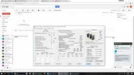
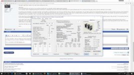
On image all so you can see calculation for PC40 and for ZP40 ferrite core , zp 40 have more flux density , that is 0.534 T .
This is calculation with PC40 ferrite core :

This is calculation with ZP40 ferrite core calculation :

I think that is problems with transformers calculation and have same problems like Tomek , PCB is redesigned and I think that is not problems with circuit .
Silvio , can you compare that with data in attachment and see what we do wrong with calculation ?

I m first calculate with core data from epcos PC40 feritte , today I m receive new info for core producer and add it , now need be sure that all is correct and then wind new transformers .
On image all so you can see calculation for PC40 and for ZP40 ferrite core , zp 40 have more flux density , that is 0.534 T .
This is calculation with PC40 ferrite core :
This is calculation with ZP40 ferrite core calculation :
I think that is problems with transformers calculation and have same problems like Tomek , PCB is redesigned and I think that is not problems with circuit .
Silvio , can you compare that with data in attachment and see what we do wrong with calculation ?
Attachments
-
 proracun smps trafica.jpg20.9 KB · Views: 7
 -
 old transformers calculation.jpg20.5 KB · Views: 9
 -
 new transformers calculation.jpg21 KB · Views: 10
 -
 core data.jpg19.5 KB · Views: 6
Last edited:
Silvio
Well-known member
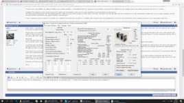
Mojalovaa What type of converter are you making and what topology? The bottom tumbnails are too small to see
As a general rule the winding fill factor must not exceed 0.3 as leakage inductance starts going high above that. The coupling between windings will also get worse and loses start to rise. Try to fit your windings in a single layer as much as possible. You must keep the coupling tight between windings and use the full width of the bobbin. Take a look at the blog post regarding winding practices for smps by Silvio on this web site. You can also take a look on Youtube for winding transformers for smps by Silvio De Leonardo. This will give you a good idea how to fit your windings on the bobbin.
I hope that helps
Last edited:
Hi Silvio , I m winding transformers for my flyback smps 500W .
I m wind my transformers wire to wire how much can do that , on primary side that is 2x0.45mm diameter wire 58 turns ( 2 x 29 turns ) , for secondary I m use 6x1.15 mm diameter wire ( 5 turns ) , for pwm chip supply from transformers I m use 0.32 mm wire (4 turns ) .
Only supply for PWM is not winding wire to wire , have 3 mm distance because I m won that wind go how much more is possible long like other wind .
Next post will be to my post : http://www.diysmps.com/forums/showthread.php?890-diy-500W-smps-with-voltage-or-current-regulation
Silvio
Well-known member
Hello Mojalovaa, I am not so keen with flyback design and I guess you are trying to get quite some power for a flyback. Just remember that the power has to go with one transistor powering it all. I think it will be better for you to use half bridge topology instead. It will make your life easier for you until you get to the end result.
Hi Silvio
In the last time I rewound the transformer and here are the results:
As a load I used 7 series of 0.47 Ohm resistor dipped in a glass of water.
Without the output choke I got 34V on the resistor which gives 350W and 10.3A but that is not the result with the 320VDC power supply. The autotransformator I had set for some 200VAC ie it still lacked 30VAC is the nominal inverter power supply.
Increasing the voltage caused the transformer to squeak even though I laid a thin layer of cyanoacrylate on the sides of the core (not between the cores).
Also, after the waveforms on the oscilloscope, it was evident that weird pins appeared and overall the course was crazy and hopping. Unfortunately I do not have a photo.
I know I should test at nominal mains power, eg by bulb in series, but with these powers I was more comfortable using autotransformer.
The next test I did with the 10uH output choke and I got the maximum power of 204W, 26V and 7.85A when the inverter was powered by 320VDC
The chart below[transformer ]:

http://fotowrzut.pl/SI6D0MCU9W
Since the core does not want to move anymore like 350W it is not a problem with too large 0.2T induction? Many people on the Internet recommend 0.14T or 0.15T
Silvio you met with the winding of the primary winding, which consists of two parts but they are connected in parallel and not in series as you suggested me a few earlier?
In the book Power Supply Cookbook 2nd edition Marty Brown is shown. The primary windings have an appropriate number of coils (calculated value) and are connected in parallel.
Why in the ATX snubber computer power supply is at the transformer and not at the transistors?
In the last time I rewound the transformer and here are the results:
As a load I used 7 series of 0.47 Ohm resistor dipped in a glass of water.
Without the output choke I got 34V on the resistor which gives 350W and 10.3A but that is not the result with the 320VDC power supply. The autotransformator I had set for some 200VAC ie it still lacked 30VAC is the nominal inverter power supply.
Increasing the voltage caused the transformer to squeak even though I laid a thin layer of cyanoacrylate on the sides of the core (not between the cores).
Also, after the waveforms on the oscilloscope, it was evident that weird pins appeared and overall the course was crazy and hopping. Unfortunately I do not have a photo.
I know I should test at nominal mains power, eg by bulb in series, but with these powers I was more comfortable using autotransformer.
The next test I did with the 10uH output choke and I got the maximum power of 204W, 26V and 7.85A when the inverter was powered by 320VDC
The chart below[transformer ]:
http://fotowrzut.pl/SI6D0MCU9W
Since the core does not want to move anymore like 350W it is not a problem with too large 0.2T induction? Many people on the Internet recommend 0.14T or 0.15T
Silvio you met with the winding of the primary winding, which consists of two parts but they are connected in parallel and not in series as you suggested me a few earlier?
In the book Power Supply Cookbook 2nd edition Marty Brown is shown. The primary windings have an appropriate number of coils (calculated value) and are connected in parallel.
Why in the ATX snubber computer power supply is at the transformer and not at the transistors?
Last edited:
Silvio
Well-known member
Hello Tomek,
Regarding the wave form shown in the attachment it seems ok and with a good shape. Having put your output inductor yes its true that the output voltage drops and hence also the total power for the same load. If you want to regulate your smps it is important that you have an output choke otherwise the pulse width will be very narrow on minimum load and the trafo tries to saturate with a narrow pulse width. A compromise have to be set regarding minimum load and maximum voltage drop. The lower the minimum load the higher the inductance in the output choke need to be , this in turn brings more voltage drop on the output at maximum load. Your tests are showing you that for the same output voltage you need to have more headroom so that it can compensate for the output inductance at maximum load.
Transformer squeaking This is showing you that your B is too high at maximum voltage of 230 volts. I forgot what type of core material are you using but it is clearly shown that saturation of the core is present at maximum voltage input. To cure it you must add more turns to the primary winding. You can easily find the amount of added turns needed by proportion, Eg, for 200v you need 20turns so for 240v you need how many? so multiply 240 X 20 divided by 200 = 24 turns. I am afraid that you have to rewind the trafo again according to the new ratio as the volts per turn has now changed. calculate your turns at the maximum input voltage because mains voltage fluctuates up and down. see that you also have enough headroom on the secondary at minimum input voltage.
Work out your findings and see what is the maximum voltage drop that you have and convert it to percentage in relation with load and no load. Having this answer in your hands will guide you to add necessary headroom in your secondary so that you can achieve the maximum voltage at the maximum load. Through the little experience that I have I found out that without output inductor the output voltage will sag to around 15-20% at full load. With the output inductor fitted it will rise to around 30% more headroom and this also depends on the inductance of the output choke besides construction of the trafo itself and also the current density used in your copper wire. For current density of the copper wire do not go above 6amps per mm^2 as voltage drop due to copper losses will come into play at maximum load.
Regarding the comment about the coils in parallel instead of in series well I think you misunderstood. The number of turns needed have to be there no matter if you put two wires in parallel or even 3 or 4 the amount of coils in parallel are there to carry more current more than anything else.
The snubber on the ATX supplies are across the trafo primary well like that they use only one capacitor and one resistor. Just remember that if you put the snubber across the transistors the load on the snubber resistor will be half of what is used when it is fitted on the primary. Each snubber is now only suppressing half the pulses. If there is good construction of the trafo with low leakage inductance the snubber value does not have to impose a heavy load to dump the spikes and in turn the resistor will be lower in wattage. The snubber can then be fitted across the trafo primary.
My last comment Well now that you managed to wind the trafo correctly you are seeing a better wave shape with less spikes.
Last edited:
Hi Silvio
The tests were carried out without feedback and until I reached the expected output power I would not be doing it.
The core I use is 3C90, primary winding 22 coils, secondary 2 x 7 coils.
I made a dump of the oscilloscope when the oscillation starts:
http://fotowrzut.pl/QU8VMOYCDH
With regard to the book Power Supply Cookbook - Second Edition By Marty Brown and the combination of the two halves of the primary winding in parallel this picture depicting such situations is on the 125 page hence my question about such a connection.
Silvio
Well-known member
Hi Tomek I can see that the pulse has a kind of symmetry there is one good pulse the second one is a bit distorted from the top and the third is full of oscillations. This pattern is starting all over again. I was just wondering where you where measuring during this shot. It seems rather odd though as this kind of pulse is not accepted Things should be constant all the way not changing shape every three pulses.
I can also see that the switching frequency is 45Khz. Your design frequency is 50Khz. It will be ok if you go a little above the design frequency but not below as the flux density will rise
Regarding the secondary output I suggest that you hook them up in series. Put the center tap as ground and then connect 2 fast diodes (one on each end) at the remaining 2 ends. connect the output from the diodes together. There you will have your positive. I think that is the best way to connect them.
Regarding Primary winding it could be the case that he had the full number of turns in each layer, now having one full winding in the bottom and another full winding on the top of the secondary windings, I am afraid of this situation but because the outer winding will be somewhat longer and the resistance of each winding will not be equal.
Last edited:
Hi Silvio
The attached oscilloscope waveform comes from the primary transformer winding
I soldered the potentiometer instead of the resistor Rt so as to smoothly adjust the switching frequency. At 50 kHz on the primary winding there are also distortions that I described in the previous post.
I have observed that the higher the switching frequency, the lower the voltage on the load. Although I will add that the transformer gets warm up quite quickly regardless of the set frequency. Even at 50kHz it gets pretty hot quickly.
Probably actually something is with the transformer induction right? Maybe try to rewire the transformer again but already at 0.12T eg?
Silvio
Well-known member
I would like you to try something else. I think that your signal to the fets is being disturbed and hence the oscillations and wave forms are not constant. If you have an old trafo from an atx power supply try to hook it up instead of your trafo. These smps are normally working at around 20Khz so the primary inductance is more than enough, see what happens.
It could be that your transformer windings have a shorted turn somewhere. Again if you have an old atx computer supply just adjust the switching frequency and try out your trafo on it.
One last thing you can try an IR2153 to drive your mosfets. hook it up on a piece of veroboard and switch your fets with it.
one other idea that is crossing my mind is to hook up a 100 watt bulb rated at 110v instead of your transformer primary and see the wave forms on it, If the voltage rating of the bulb is 220 volts do not worry try it just the same as it will draw less current, This way you see if your switching arrangement is ok or not.
If the trafo is getting hot very quickly then for sure its either the wave form is not good or the trafo itself may be shorted somewhere.
I hope that you connected the 2 half primaries on your trafo in series and not in parallel,
I cannot think of anything more to help you out, I never had these kind of issues in my DIY
Regards Silvio
Hi Silvio
I rewound the transformer, 30 turns to the primary and every secondary to 8 turns. The core has been glued with cyanoacrylate. And yet the core at high load was vibrating. Probably the winding is so twitching. I will do a test on one transformer and try to completely glue it.
In addition, I guess I burned the SG3525, the internal oscillator can not stand up.
Now it comes to me to re-design the PCB and continue to fight. One thing I know is that I will try until I reach my goal. Once I reach the goal I will write where the problems lie, and so on.
For the moment, thank you Silvio for the great help.
Silvio
Well-known member
I have worked with SG3525 and my high and low side driver is IR2110 it works very well and I had no problems. The IR2110 has a driving capability of 2 amps and is very rugged. You can use my schematic for the design in my 1000 smps. You can find the whole pdf on this web site with full schematic and pcb layout. I suggest you go for ludo3232 design for the PCB as my PCB is not up to standard regarding spacing between high and low voltages.
Good luck and regards
Good luck and regards