Snubber calculation...

blasphemy000

New member
Just a quick question about snubber calculation. How do you do it effectively or is it more of an art? I've built a few SMPSs but they were all based off of other people's designs with minor tweaking so I just used the snubber values that they provided. If I'm designing a power supply from scratch, how do I calculate these? This is for my welder project but if there is some sort of formula then it can be applied to other power supplies as well.

Attached is an image of a very simple example Full H-Bridge driving a switching transformer.
How do I calculate R1-4/C1-4? How do I calculate the subber on the secondary side of the transformer, R5/C5? And also, how do you calculate R6 and what is it's purpose? I've seen R6 on some supplies and absent on others. Also, lets assume that the IGBTs have internal diodes. For my welder the peak bridge current will be 50A at full power and the IGBTs will be multiple paralleled devices...
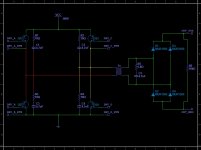
Example Bridge.jpg
 

ultra

Member
R6 is to discharge the capacitors, that is why it is absent in some circuits (they dont really care).

R5/C6 purpose is to minimize transformer overshot and (unfortunately you need to test values at full power).

There are a few pdfs about how to calculate the values, but-in my opinion-the best way it by experimenting on the bench.

You can start with eg 100R/2W and 10n and see the overshot. Then you can increase the value of the capacitor to 15n etc
 

KX36

New member
Standard procedure for designing an RC snubber to damp a ringing LC tank is very simple. R in series with C, both in parallel with the ringing capacitance (e.g. a PN junction capacitance) R is the impedance of the L or C at resonance, C is significantly greater than the ringing capacitance so that it doesn't have much impedance at the resonant frequency, but too much capactiance here can decrease efficiency.

So what if both the ringing C and L are parasitic and you don't know their values, e.g. from a reverse biased diode's junction capacitance and a transformer's reflected leakage inductance? If your circuit can tolerate temporarily running with no snubber; measure the ringing frequency, add capacitance until the ringing frequency halves. The capacitance you have just added is 3x the parasitic capacitance, so you can calculate the parasitic capacitance and inductance and their resonant impedance and use that to size R. The capacitance added is usually OK to leave as the snubber capacitance.

Simple :)
 

aharon.fin

New member
Just a quick question about snubber calculation. How do you do it effectively or is it more of an art? I've built a few SMPSs but they were all based off of other people's designs with minor tweaking so I just used the snubber values that they provided. If I'm designing a power supply from scratch, how do I calculate these? This is for my welder project but if there is some sort of formula then it can be applied to other power supplies as well.

Attached is an image of a very simple example Full H-Bridge driving a switching transformer.
How do I calculate R1-4/C1-4? How do I calculate the subber on the secondary side of the transformer, R5/C5? And also, how do you calculate R6 and what is it's purpose? I've seen R6 on some supplies and absent on others. Also, lets assume that the IGBTs have internal diodes. For my welder the peak bridge current will be 50A at full power and the IGBTs will be multiple paralleled devices...

View attachment 4388


see this link:
http://www.maximintegrated.com/en/app-notes/index.mvp/id/3835
 

KX36

New member
So... good to know in the year since I posted the answer and this thread ended, the procedure for calculating a snubber to Q=0.707 hasn't changed as that maxim link is the same as what I said... don't really see what extra info it adds.

I would add you don't even need to use that relatively complicated formula to calculate the parasitic inductance. Knowing the parasitic capacitance and resonant frequency you simply have to calculate capacitive reactance and that will be the value of the resistor.
 
Top