DjLeco
Moderator
On air, spider montage testing:
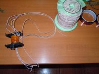
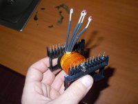
Rezonant mode, half bridged IRG4PC50W IGBT's ETD59 core, 3C90 material, 600x0,071 litz for primary winding , 2x200x0,08 for secondary winding,maximum randament achieved ay 55 Khz (don't know why)...
Tried more or less spires for primary, in any case, maximum randament achieved @ 55 Khz...
Someone can explain that?
Why doesn't want to give maximum randament at 80-100-125 Khz, instead 54 Khz??
Movie during testing:
[video=youtube;ZRIuq4J7CrE]http://www.youtube.com/watch?v=ZRIuq4J7CrE[/video]
 cool link