Hello. I'm not sure if section correct, if not please tell me.
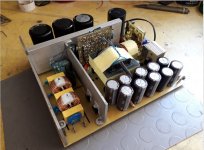
Since my start with electronics ( I was 10 years old ) I used simply SMPS like LM2575 or so, to power microcontrollers or other stuff - these chips was simple, and resolving any problems took like minutes. Last year I wanted to start with mains-powered smps, so I took simply design from this page: https://www.hobbyelektro.eu/spinany-zdroj-0-30v-0-6a/ Why this one? becauose it's almost identical to old ATX 200-300W supplies, which i can buy from scrapyard and get components. Everythink went well till i powered it up. there were some minor issues which were solved fast, but then I realised one big problem: In certain duty cycles converter is kind of buzzing or so(but overall regulation was good and also claimed power was easy achieved). And also when it's in one of these spots main transistors are heating extremely, Problem is not on full power, it's like in some points of regulation. I started digging in to this subject and simplified schematic to what's in attachment (I made it to ensure that wasn't feedback etc.). As 15V source I use lab bench power supply( it's factory one - 100% good ripple and things like that). Now I'm generating duty cycle from 494 (on separate board )and It looks ok, but as mentioned on some duty cycles it's going crazy. I'm using base-drive transformer from working ATX of exactly the same topology, main transformer is rewound, but exactly the same happened when I connected main transformer from ATX (on 12V windings). For test i've got 5 ohm load to prevent saturation of transfromer. Also when I increase auxiliary 15V to about 20V buzzing goes to higher freuencies, but transistors heating the same. And also, when it's not buzzing transistors are heating only a little bit( as expected ). And You know what is worst in all this: Every chinese stupid power supply works on exactly the same schematic (primary side) and I can't get it to work. I spent houndrets hours reading about this topology, I can tell what every component is doing in this supply, but I can't get it to work properly. Is this frustration?
I will provide You any kind of resources: photos, simulations, sreenshots from oscilloscope(digital or analog), but please HELP!!!!
Also sorry for my english - I'm from Poland.

when it's not visible - there is link: http://fifi.starkom.eu/rahchat/uploads/1587928621.png
Since my start with electronics ( I was 10 years old ) I used simply SMPS like LM2575 or so, to power microcontrollers or other stuff - these chips was simple, and resolving any problems took like minutes. Last year I wanted to start with mains-powered smps, so I took simply design from this page: https://www.hobbyelektro.eu/spinany-zdroj-0-30v-0-6a/ Why this one? becauose it's almost identical to old ATX 200-300W supplies, which i can buy from scrapyard and get components. Everythink went well till i powered it up. there were some minor issues which were solved fast, but then I realised one big problem: In certain duty cycles converter is kind of buzzing or so(but overall regulation was good and also claimed power was easy achieved). And also when it's in one of these spots main transistors are heating extremely, Problem is not on full power, it's like in some points of regulation. I started digging in to this subject and simplified schematic to what's in attachment (I made it to ensure that wasn't feedback etc.). As 15V source I use lab bench power supply( it's factory one - 100% good ripple and things like that). Now I'm generating duty cycle from 494 (on separate board )and It looks ok, but as mentioned on some duty cycles it's going crazy. I'm using base-drive transformer from working ATX of exactly the same topology, main transformer is rewound, but exactly the same happened when I connected main transformer from ATX (on 12V windings). For test i've got 5 ohm load to prevent saturation of transfromer. Also when I increase auxiliary 15V to about 20V buzzing goes to higher freuencies, but transistors heating the same. And also, when it's not buzzing transistors are heating only a little bit( as expected ). And You know what is worst in all this: Every chinese stupid power supply works on exactly the same schematic (primary side) and I can't get it to work. I spent houndrets hours reading about this topology, I can tell what every component is doing in this supply, but I can't get it to work properly.
Is this frustration?I will provide You any kind of resources: photos, simulations, sreenshots from oscilloscope(digital or analog), but please HELP!!!!
Also sorry for my english - I'm from Poland.
when it's not visible - there is link: http://fifi.starkom.eu/rahchat/uploads/1587928621.png
Last edited: