Tube amp SMPS

miniman82

New member
MicrosiM said:
Looks like you are attempting to build SMPS without any knowledge about how it works. I suggest you to read the safety paper here, SMPS is not your weekend project to play with.

Please don't make the mistake of assuming what I know/don't know, you don't know anything about me other than what I've said here. I have plenty of experience in other areas of the field, and am competent enough to read a data sheet and get something to work. If I weren't, I wouldn't have even gotten this far...right?

Its only one mistake, and you may not live to regret it. We are all here to help, this (is not?) place for those with minimal experience in the high voltage stuff. If you don't have that, I suggest you to read about SMPS for a while before any attempts. This thread / your account is subject to be closed the minute I see its too risky for you.

Excuse me, but you're going to have to give me a little more credit than that. I'm not some electronics noob who just wandered in here splicing MOSFETS and transformers together to see what will happen. I mean, that's kind of how it happened, but there was actual thought behind it. I understand your concern, but it's completely unfounded. I have to chuckle a little each time someone calls 400v 'high voltage', seeing as the vintage vacuum tube based flybacks in my TV collection all operate north of 23kv and those haven't killed me yet. THAT'S HIGH VOLTAGE! Lol

I work with HV quite a lot, frankly there's more to fear from the linear B+ supply in one of my old guitar amps than there is in this switching supply. I'll be fine, I think once I put a schematic up things will become much more clear. And if it's not a good design this time around, I'll learn from it and build a better one next time. Like Edison.
 

blasphemy000

New member
http://www.diysmps.com/forums/showthread.php?522-Calculation-programs-for-transformers-and-inductors

I forgot about these. The person that designed the transformer calculator also designed some other magnetic calculators. There is a Flyback one in there also. I've never used it, but it should work similarly well to his other programs.

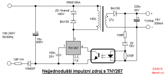
The primary clamping components aren't optional. The supply might sort-of work without them, but it won't work correctly and will lead to you chase your tail trying to solve other problems that are only there due to lack of primary clamping.

A simple Zener clamp is the easiest to implement and works well in many situations.

The IRFZ46N that you're using has a VDS breakdown voltage of 55V.
We'll use 45V as the maximum voltage that we want on the Drain of the MOSFET. That way you'll have about 10V for error.
If your maximum input voltage is 15V. That leaves 30V that can be allowed across the primary at turn-off.
You can use a Zener diode with a voltage of around 28V. The 1N5362BG is a 28V 5W device that I imagine could work.
For the switching diode, any 1A rated ultra-fast diode should work. BYV26 series are good, but there are tons of other ones that would be equally good.
With the combined voltage of your 28V zener diode and the forward voltage(Vf) of your switching diode, this will give you around 30V and when added with your 15V input voltage should clamp the voltage at the drain of your MOSFET to ~45VDC.
Just arrange the diodes as they are in the attached schematic. Don't worry about the rest of the schematic, just the primary winding and the 2 diodes that are attached. At least this way you'll have some sort of primary clamping going on.
Simple Flyback.png
 

miniman82

New member
I assume the clamp protects the primary MOSFETS from inductive kickback that may exceed VDS? Probably a good idea. Side note: the 1200v rectifiers came the other day, 400v portion of the power supply is now working. Has a slight overshoot on startup as the secondary side caps charge, I can probably cure that with either smaller caps (10uf vice 33uf), or maybe a longer soft start period would do the trick. Meh, more futzing will take place this weekend if I get the time.
 

blasphemy000

New member
I assume the clamp protects the primary MOSFETS from inductive kickback that may exceed VDS? Probably a good idea.

Yes, that is one of the necessary functions that the clamp provides. Providing protection to prevent exceeding the VDS(br) rating of your switch.

The other function it provides, is to discharge the leakage inductance of the transformer. This energy needs a place to go and it will find one. It will dissipate as primary oscillations as it interacts with stray capacitance, it can cause a large voltage spike that exceeds VDS(br) and dissipate through the switch, or it can build up and cause saturation. A primary clamp provides a path to allow it to be safely and quickly dissipated.

Again, a primary clamp of some sort: Zener clamp (like the one I showed and explained above), RCD clamp, RDZ clamp, ect., is not only a good idea, it's a requirement. It must be there for proper function.

As an additional note though, ignore my previous post about HOW I calculated the clamp voltage for your primary. I forgot to factor in the reflected secondary voltage and the turns ratio to ensure the clamp voltage was higher than that. The need for a clamp and the effectiveness of the zener style clamp still stands, I just calculated what the clamping voltage should be. My apologies.


Side note: the 1200v rectifiers came the other day, 400v portion of the power supply is now working. Has a slight overshoot on startup as the secondary side caps charge, I can probably cure that with either smaller caps (10uf vice 33uf), or maybe a longer soft start period would do the trick. Meh, more futzing will take place this weekend if I get the time.

A longer soft-start would probably help with the overshoot. The other issues should be solved first before dealing with the output response.
 
Top