Vacuum Tube SMPS

printer2

New member
The lengths that I will go through to save a couple of pounds of iron. Got it in my head to build a (roughly) +350V 0.1A, 6.3/12.6V supply for a guitar amp. Want to use a TOP202YAI, http://dalincom.ru/datasheet/TOP202YAI.pdf . Thought of grabbing a core and input bits from an ATX ps.

Been sifting through threads here which prompted me to look up datasheets, I have a lot of learning to do. I do have a background in electronics, blew up my share. Mainly into tube amps for now, the paltry 20W amp I want to build seems rather out of place with you guys doing 1kW supplies. Parts are coming on a slow boat from China so not a lot will happen quickly, give me time to figure out what I really am doing. Hopefully you guys can keep me from doing anything really wrong. In return I might give you something to laugh at.
 

lynxlynx

A rumbling soft motor
Your power requirements are adequate for flyback supply, but output voltage will not probably fit. If you want to use flyback type, then for your +350V output you will need probably five-ten times higher rating output diode, i.e. 1-2kV. It's common for flyback supplies output of 24V for example to have 100V output diode and more. You can vary this voltage by increasing primary inductance, but this will also put a stress on primary switching element, however, decreasing current.
 

printer2

New member
Hi, thanks for the response. I am new at this so I expect to take some wrong turns, learning something new sometimes has bumps in the road. I tried to find a circuit to do what I want and came up empty handed, might just used the wrong search terms. I was going to go real cheap and dirty taking two SMPS's, take the transformer out of the one and step up the voltage by connecting the low voltage sides of the transformers together. Then there was the idea of using a 30V PS and hook a 10X voltage multiplier to the secondary. Just need a bunch of fast diodes without a high voltage rating.

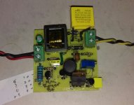
But I had a SMPS built for an alarm system battery charger using the TOP202YAI. It had some fried bits at the alarm portion of the circuit board but the supply works. So I thought to keep it intact as a working example of what the circuit should be doing if I do my own variation of it. Otherwise I am winging it. I know I have no clue if a transformer from a computer supply would work with the chip. Might be the wrong frequency range, wrong inductance if wired up for my application. It is best to say I kind of know how much I don't know. I should scope out my alarm ps board but too busy getting some guitars done (amateur builder). I did look for some diodes for the secondary, found the BYV26G, not sure if it will be fast enough or have a high enough voltage rating. I hope to find a different one as I would have to buy 10 and it starts to get pricey.

http://www.gulfsemi.com/Upload/BYV26G.pdf

Found a BYT54M 1000V 1.25A, not sure if that is good enough voltage wise or speed.

http://www.vishay.com/docs/86031/byt54a.pdf

Could do some more searching, seems like I should be able to find something. Really the black hole of my knowledge is in the transformer. Not a surprise I guess.
 

lynxlynx

A rumbling soft motor
I did some "example" calculations and I can say it will work if you will go with 1400V one. It nicely fits into requirements + some safety gap. I did calculation if I would to build it today with my "example" transformer. Primary switch voltage is about 600V and secondary diode voltage is 920V and peak currents are in safe limits. 100nS recovery is fine if you will not overdrive it with hundreds of kHz, 100kHz of TOP is fine I think. I did used FR207 with it's 500nS with 100kHz and it did worked, but in other switching circuits it will blow.
However if I wanted to design such a circuit I probably would go with separate voltage for second small push-pull supply that will provide +350V separately. I would power it from either 12 or up to 20V because of gate voltage. Just it's hard to find really high voltage fast type diodes there where I live and long waiting for them to be shipped. It's also more safer. And overpaying for damper diodes when I can buy some MUR460 which are proven fast and stable (however you will need 2 or 4 of them ;) ).

Flyback transformer is indeed complex thing. You need to be cautious when you select primary voltage because you need to send all of parasitic kickbacks into it's RCD snubber across primary so it will not kill your switcher. You need to pick up current protection resistor if you build it discrete type/UC384x, which is also sometimes maybe a hard task (but you're using TOP, so you are safe). All switching and rectifying elements must have avg. 2-3 times more ratings than your requirements (voltage, current) because of how flyback works - delivering energy by short but hard spikey packets. However you can vary impulse duration.
It's not like you can salvage random transformer from ATX. I think you will need to rewind it. If you thinking about taking main transformer then do not ever do that without creating a gap with paper between halves - it's usually gapless and you will need gap in your transformer core. In fact, flyback transformer is just an multiple winding inductor and it needs to be protected from saturation.

If you do not know how flyback transformer work, you can try to simulate it. Download LTSpice and I will send you an example (or even example for your +350V needs). For transformer calculations, seek for Starichok51 Flyback program. I have another calculator, but it's text mode based and still experimenting with it. I hope TOP has programs for it and you will probably skip all this nightmare of picking up random parts :)

For this task you probably will need LC meter otherwise it's going just to be guessing and burning parts. Oscilloscope also is a very good option, but only with 100x probes!!!
 
Last edited:

printer2

New member
You have been working overtime. I think there is a program from the manufacturer to select the transformer. Did a little reading the last day or so, you SMPS people are insane. I can find my way around the average schematic but this stuff is almost in the realm of black magic. Guess the programs help. I do have LTSpice on one of my computers, never really found the time to really learn to use it. Might as well jump in with both feet.

I assumed I would have to wind my own transformer, was hoping to do a lower voltage test circuit and then up the voltage a few times till I get close to my target. I could be wrong but I get the feeling adding some windings will change the parameters of the transformer and might throw off the circuit. I have been trying to figure out the size of transformer needed and looking on EBay to see if there is one to be had at a reasonable price. Saw this, don't know enough if it is something I want or not. While I am all for being thrifty and recycling stuff I won't know what I will be getting out of my junk pile. If it saves me grief I could pick something like that up.

http://www.ebay.ca/itm/161946238423?_trksid=p2060353.m1438.l2649&ssPageName=STRK:MEBIDX:IT

I have a DMM that will measure capacitance and inductance. Don't have the 100X probes but I can hit up my brother when I get that far, one of the products the company he works for is a fencer to keep animals contained. A few loops of small gauge wire should be no problem also.
 

wally7856

New member
"I assumed I would have to wind my own transformer, was hoping to do a lower voltage test circuit and then up the voltage a few times till I get close to my target."

This is a very good idea. Start with a 12 to 24 vac transformer to power your flyback and make lower output voltages. Now you can poke your fingers all over the circuit and use regular scope probes.

The transformer you picked out on Ebay is probably good for 30 to 50 watts and has a fair price. It has a lack of specs but the one you need the most is there. AL=2850±25%.
 

printer2

New member
Well that is great, one less thing to scratch my head about, I'll pick up the cores. Good to know I can muck around at lower voltages. Not too squeamish about higher voltages, play with my tube amps and need to troubleshoot 600V stuff at work. Have a healthy respect for HV, haven't got poked by it yet, 120V a few times.
 

printer2

New member
Been looking at diodes I can get and thought about a couple of UF4007's in series. I already have some, any problem using them?
 

lynxlynx

A rumbling soft motor
Maybe, because diodes are not resistors or other such passive components. They can slightly differ in specs, resulting in one diode taking all voltage on itself and burning because of result overvoltage (same applies to current rating). If you concerned, you can put 100k-1M resistors across each diode. And UF4007 was not good for me, they nicely overheat and puke already at 400mA 50kHz for me (because of their poor forward voltage and very small size for this dissipation). So watch not to overload it.
 
Last edited:

printer2

New member
I'll keep an eye out for another diode, the 1500V one is only sold in a group of ten and if I were to make a number of PS's I would go for it but I am doing this more of a proof of concept exercise. Or in another words, I get an idea and then want to see if it is doable. I know about balancing resistors across the diodes, hope to keep the average current below 100mA.

HER308 is reasonably priced but need to do two in series. 1000V 3A 75nS

http://www.rectron.com/data_sheets/her301-308.pdf


RHRP15120

http://www.farnell.com/datasheets/1783739.pdf

1200V 15A 75nS, does not look too bad. So some options. Will have to think more on this this weekend.
 

lynxlynx

A rumbling soft motor
Some free parts can be obtained from old & burned units: ATX supplies, (not so) old TV sets etc. It's main source for me except very expensive things required by my big projects.
 

printer2

New member
Had an idea to reduce the peak voltages involved. I don't see any downside yet, thinking of reducing the voltage out of the transformer by half and using a voltage doubler on the output to get the 350V (might even go higher now :) ).
 

printer2

New member
Had an exciting day at work, well sort of exciting, more like it better than usual. First I have this big old junky tube radio sitting on my chair. Somebody was tossing it out and thought I might like to gut it first. Got a power transformer (in the picture) a small output transformer and an interesting grill cloth I might use. I also stumbled on an electronic ballast for florescent lights that was no good. I popped it open to see what is inside. I instantly thought high voltage SMPS, then I thought to track down an electrician to see if they had some more. Seems we have an assortment. I see hours of amusement here.


printer2

New member
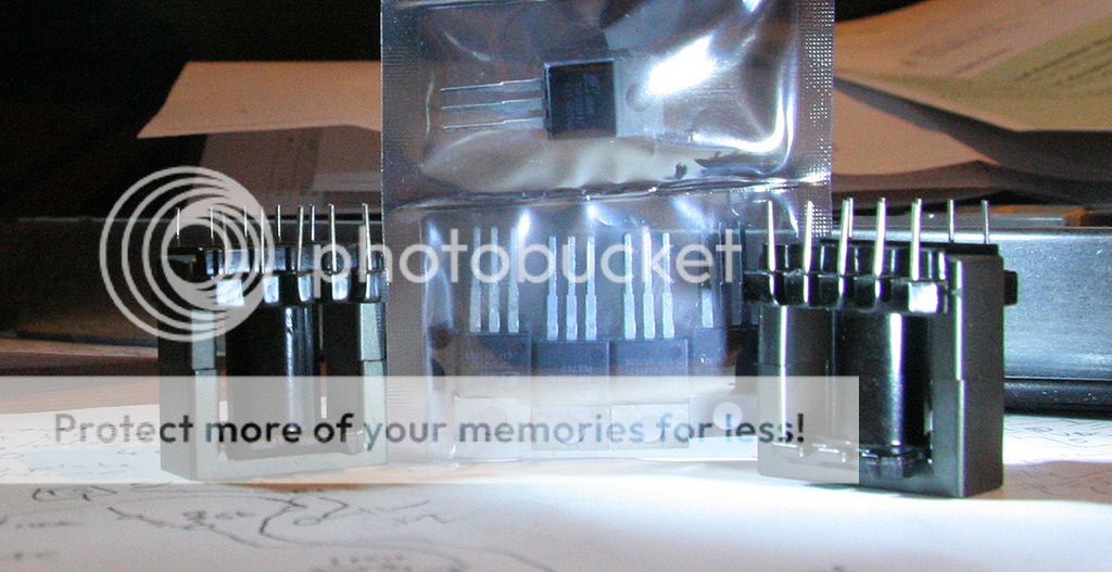
Well I knew a switching supply will shrink the iron (do you still call it iron?) but I was not expecting this.


Both my packages came today. I guess I really going to have to start thinking about how I am going to do this. Redesigning an amp at the moment so I'll just have to put these on the shelf.
 

Triode

New member
I built a miniature adjustable tube B+ supply based on a current fed royer oscillator. It provides 100-200v at around 20mA. A little small for your needs,but it can be scaled up pretty easily.

I run mine at ~200kHz to be way above the audio frequency range, and since it is a sinusoidal oscillator it is much lower noise output than hard switched topologies like boost. This technique is outlined in a Jim Williams paper on high frequency, low noise stepups.
http://www.linear.com/docs/26421

Here is a pic of my mini unit. The oscillator transistors are only 2N2222, the current sink is IRFZ44, the regulation is via TL431.

IMAG0280_1.jpg

I'll post more later, but I wanted to mention it because some of those ballasts look like they may also be self-oscillating like mine. You might be able to reuse one of those transformers as-is. Do you have an LCR meter to test them?
 
Last edited:

Triode

New member
OK, the circuit I built is a simplified derivative of the Jim Williams ckt on p2 of that app note I linked. And basically made of all junk bin parts, so component values were not critical and some changed during the build. :)

View attachment 5883

The topology is "current fed royer" - by adjusting the tail current through the oscillator, the output voltage can be regulated. A three-coil transformer was wound on a tiny unknown core with normal AL=1400, but I gapped it by 2x0.1mm (sticky paper) to result in an AL around 200 and a saturation current of more than 5A. If I had thinner paper, I would have gapped it less! :) The transformer is 10T (5Tx2) center tapped primary, 4T aux (base drive), and 200T (100T x 2) secondary. This ratio was chosen to give >200V out when fed from 5-12V, but since I only had a 10k pot on hand my circuit here only has an adjustment range from about 100-180V.

10T primary and 200nH/T^2 gives a 200uH primary, so I set the resonator cap to 6.8n for about 136kHz. It ended up more like 170kHz, which is fine. Probably my trafo taping was weak so my gap was wider, and AL lower than I expected.

Regulation is through TL431 and the NMOS used to set the oscillator current - when the voltage feedback reaches 2.5V, the NMOS gate voltage is reduced and the oscillator current is throttled down. My circuit is currently using 1.6k for 2n2222 base drive to force the beta to around 50-60, and the 270 Ohm pullup for the NMOS was an experiment to lower the TL431 AC gain - it's not necessary to use this small of a value. 1k should be fine. The TL431 is compensated with 1n cathode to FB, and a 200pf feedforward on the top 1M feedback resistor completes the AC response.

By fooling with the secondary turns, you could easily change the output voltage working range to something entirely different. But for slight adjustments, we can just change the feedback resistors. I'd leave the top one at 1M to avoid adjusting the 220p feedforward, but the lower feedback resistors could be anything. The lower feedback resistors are made of two parts: A fixed resistor to set the absolute maximum output voltage to avoid blowing up the rectifier diodes, and a potentiometer to give some output adjustment - it's fine to also use a fixed divider for a fixed output.

I use this supply for playing around with russian subminiature tubes like 6n16b, and it happily delivers a watt or two at 120-150V. Due to the TL431, the regulation is actually quite good.

Attached are the schematics and pdf of the pcb, along with the ltspice schematic I use for experimenting.

EDIT: Oh yeah - one mistake in the eagle schematic - I forgot the 1n compensation on the TL431! That's why it's soldered directly the the TL431 pin, ha ha. I should probably fix that.
 

Attachments

  • MiniB+SCH-PCB.zip
    66.1 KB · Views: 46
Last edited:

printer2

New member
That's it for a schematic? And it self-oscillates? Heck, my first amp turned into an oscillator so even I could probably do it. Going to have to look at the parts I have closer.

Seems the Power Integration chips I got can be particular on what transformers they want to work with, the company says to not bother with the chips as they are an old design and the new stuff is much better. Mind you their software did not care too much for the transformers I have for the power level I want to get out of them. So now I have a wide open field to chose from in terms of design.
 
Top