Hi Lynx,
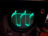
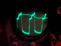
1. Ct waveform looks distorted, both amplitude and frequency is changing. Things to check: layout (interference due to high dv/dt and high di/dt, for the first one check small signal traces that are near traces with high voltage, high dv/dt traces; for the second check small loops and ground loops near loops with high di/dt), check PWM power. BTW Do you have anything connected to Pin3 of the PWM chip?
2. Probably an insulator between two cores in stacked configuration may help with heating issue. Heavy distortion could be caused by shorts in windings.
3. You can try to source hi-perm cores for GDT from old laptop power supplies (check EMI filters) or ATX power supply EMI filters. Thin multistranded insulated wire could be found in data cables for very old mobile phones
4. Since you don't have an RLC meter, I suggest you test cores like that: make test winding (5-10-15-20 turns), connect this test winding in series with low ohm resistor (like 1-2-5ohm) to some source of square wave (for example, connect it your power supply). The peak current (ignore any spikes) should be less than 100 mA.
")