Gate Drive Transformer Issues

Jagd.Panther

New member
As for driver resistors then I need 2W ones and dissipate additional 4W+. That's currently a problem... but I will try.
2 W resistors for what? You shouldn't need such resistors for any part of the GDT driver / mosfet driver.

BTW what are you working on? Is that some kind of PSU?.
 

Jagd.Panther

New member
Oh that's interesting. Datasheets often give a graphic where you see max. of 500Ohm and that's does not give a full control over dead time but I ever never experimented with that. I will try with trimmer. I need to build another one full bridge just as replacement for that 2xIR2153 thing :D

Check "Figure 2 Oscillator Discharge Time vs. Rd and Ct" in the datasheet for 3525. Choose Rd to get like 3-4us, it should be plenty to start with.
 

lynxlynx

A rumbling soft motor
2 W resistors for what? You shouldn't need such resistors for any part of the GDT driver / mosfet driver.

BTW what are you working on? Is that some kind of PSU?.

Yes I designing full bridge lab supply. It takes 350VDC input, but should run from regular AC supply. So it includes input filters. Then after rectifier a small 15V 1A flyback converter is connected to power SG3525 and driver. Then DC rail gives power to transformer via full bridge. The output should be adjustable 32-55VDC. Why I did choose GDT? Well, for safety. Then, because flyback cannot share power ground (am I right?). I am having IR2110 as an option but I plan to use them in low voltage full bridge step-up project I am collecting parts for. With driver ICs I always did had success, so I don't think IR2110 will be harder.
 

lynxlynx

A rumbling soft motor
I have datasheet that says IRFP450 has Coss 720pF. With above calculations I see it easily can break beyond 20mA. I am going to rewind transformer again and I'll see what's going on. I am having IRFP460 as an option, their datasheet says Coss only 130pF (if there are not multiple versions)
 

Jagd.Panther

New member
I have datasheet that says IRFP450 has Coss 720pF.
Yep, Vishay's datasheet says 720 pF vs ca. 300 pF for ST & IR . With 720 pF the quiscent current will be ca. 25 mA (pretty close to what you got). Do you have Vishay/Siliconix logo on yours IRFP450 (google "siliconix" logo)?

Then, because flyback cannot share power ground (am I right?).
Do you have any pic/schematic to illustrate your question on sharing grounds?


I am having IR2110 as an option but I plan to use them in low voltage full bridge step-up project I am collecting parts for. With driver ICs I always did had success, so I don't think IR2110 will be harder.
GDT + some drivers to keep mosfet closed will do the job and that approach is more robust than using 2110. 2110 dies if its high side driver potential goes lower than lower side driver by 0.6v or so (that could happen due to high di/dt, due to parasitics, etc).
 

lynxlynx

A rumbling soft motor
Yep, Vishay's datasheet says 720 pF vs ca. 300 pF for ST & IR . With 720 pF the quiscent current will be ca. 25 mA (pretty close to what you got). Do you have Vishay/Siliconix logo on yours IRFP450 (google "siliconix" logo)?

Oh... that's right, siliconix logo. So the current is purely parasitic? I was searching for a black cat in dark room then. That's why I did not see any criminal not on real circuit and not in simulations. Still new things to learn! wiz:;

IRFP460's I have are IR.

Do you have any pic/schematic to illustrate your question on sharing grounds?

See attached image. It's a real circuit without red additions. It's an example, I use IC & mosfet in one case.

GDT + some drivers to keep mosfet closed will do the job and that approach is more robust than using 2110. 2110 dies if its high side driver potential goes lower than lower side driver by 0.6v or so (that could happen due to high di/dt, due to parasitics, etc).

Yeah I know I really like GDT when you up & down mosfet in bipolar way completely closing it with negative voltage.
 

Attachments

  • dlink.gif
    dlink.gif
    38.4 KB · Views: 129
Last edited:

Jagd.Panther

New member
I have datasheet that says IRFP450 has Coss 720pF. With above calculations I see it easily can break beyond 20mA. I am going to rewind transformer again and I'll see what's going on. I am having IRFP460 as an option, their datasheet says Coss only 130pF (if there are not multiple versions)

BTW Vishay's datasheet doesn't provide effective Coss (energy related), but looking at the datasheet Coss at Vds 300V is about twice lower than specified at 25V.

Also why did you choose IRFP450? Why not CoolMOS or some newer IGBTS?
 

lynxlynx

A rumbling soft motor
Also why did you choose IRFP450? Why not CoolMOS or some newer IGBTS?

That's simple: they were only available where I live. I bought them long time ago. IRFP460 I ordered online later. What I know about IGBT's is that they good for lower frequencies...

That's strange with IRFP450, I see that in datasheet I have, at 50V in datasheet it's less than 500pF but in reality I get a parasitic current like 720pF. I really need to rewind transformer today to see what's going on with IRFP460 I have. I tested days ago with same transformer but I replaced IRFP450 with IRL1404 and gave them 12V and current was 1mA and that's indeed is what datasheet says, even better.

Btw datasheet I'm referring to is attached.
 

Attachments

  • IRFP450.pdf
    169.8 KB · Views: 44

lynxlynx

A rumbling soft motor
I had rewind transformer today.

So far is what I've observed:

* IRFP460 I have with 50kHz 350VDC draw about same current: 21mA, which is bad
* IRF730 I tested at 50kHz 350VDC draw 8mA
* IRFP460 I have at 73,3kHz 350VDC draw 32mA
* IRL1404 at 50kHz 12VDC draw 1mA (just a test)
* Adding load at outputs only adds current by current of the load
* Duty cycle does not matter, and when frequency increases the current increases too.
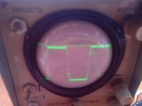
* If I give a 50kHz reference from this: http://lynxlynx.tk/log/files/_IMG_20140809_144945.jpg, I then get unusual results: 350VDC 37mA with IRFP460. I am really confused. Should my fets heat up when drawing this current? If not, them I'm not really against it, since it's not intended to be a really a high efficiency converter, but a lab supply.

So IRFP460 I have are maybe actually are remarked 450's (I got them from aliexpress) or somewhere is a mistake hides in my layout or circuit. Should I (try to) lower frequency to get acceptable results?
 
Last edited:

lynxlynx

A rumbling soft motor
Addition to previous post:

* Lowering rise & fall times increases current too.
* Mosfets do heatup of course.
 

lynxlynx

A rumbling soft motor
Removing RC in series with GDT rapidly improves rise & fall times, addition of RC filter parallel to outputs of SG3525 does indeed almost eliminate any spikes, and with addition of second RC filter 39R-100nF at GDT primary and I get a clean square wave at each gate despite selecting random core and winding as is with wires longer than 2cm. But this current annoys me. When IRF730 draw only 8mA this means I had a bad parts selection.

Can someone suggest me a better FET which is 400V <=20A Rds <=0,4Ohm with better Coss of course?
 

lynxlynx

A rumbling soft motor
This is what I get on each gate with transistors in place (50kHz RD=47R, core from photo, 22 turns 1:1 or so, Rg=10R Rgs=1k). The setup is same as I described in previous post. I replaced IRFP460 with Siliconix IRFP450 back and got a lower current now - 20mA @350VDC and they're even better than IRFP460 I have (23mA without a lamp). That's sad, but I probably will continue with them.
 

Attachments

  • 4.jpg
    4.jpg
    44.5 KB · Views: 25

Jagd.Panther

New member
This is what I get on each gate with transistors in place (50kHz RD=47R, core from photo, 22 turns 1:1 or so, Rg=10R Rgs=1k). The setup is same as I described in previous post. I replaced IRFP460 with Siliconix IRFP450 back and got a lower current now - 20mA @350VDC and they're even better than IRFP460 I have (23mA without a lamp). That's sad, but I probably will continue with them.

How do you drive GDT and how do you drive mosfets? Do use some drivers after GDT?
 

lynxlynx

A rumbling soft motor
How do you drive GDT and how do you drive mosfets? Do use some drivers after GDT?

There is no RC in series with GDT, there is two RC filters: across SG3525 outputs, and across GDT primary, both 47R-100nF. With 10R-1uF in series I get much more slow rise and fall times. Slow rise and fall times reduces parasitic current, but I worry if it can slow down fets enough to spend more time heating up.
 
Last edited:

lynxlynx

A rumbling soft motor
GDT + some drivers to keep mosfet closed will do the job and that approach is more robust than using 2110. 2110 dies if its high side driver potential goes lower than lower side driver by 0.6v or so (that could happen due to high di/dt, due to parasitics, etc).
Is there a way to prevent damage?
 

Jagd.Panther

New member
There is no RC in series with GDT, there is two RC filters: across SG3525 outputs, and across GDT primary, both 47R-100nF. With 10R-1uF in series I get much more slow rise and fall times. Slow rise and fall times reduces parasitic current, but I worry if it can slow down fets enough to spend more time heating up.
IMO there is no need to have a snubber across SG3525 output pins. Instead add freewheeling diodes (at least to ground, preferably schottky ones) after emitter followers.

The snubbers you have (47R + 100nF) look waay too heavy for the job. I'd try something like 100-200 ohms and few nanofarads if I'd really have to.

Slowing down FET's further is not a good idea, if you posted earlier a wave form on fet's gate then I'd say your rise/fall times are way to slow.

To speed up switching you can:
- decrease leakage inductance (by reducing number of turns in GDT, NB: don't saturate the core!). Ls is a major factor that slows down GDT (as it reduces current slew rate).
- decrease GDT load
- use a driver after GDT to close mosfets.
- GDT leads for every winding should be tightly twisted together

Is there a way to prevent damage?

- Carefully follow IR's guidelines on bootstrap drivers.
- Use non-bootstrap (or single) drivers with separate power supply (for example using small HF trafo) instead.
- Use GDT (it's robust, but can be slow if GDT has "large" Ls).
 

Jagd.Panther

New member
I'm attaching LTSpice draft for you to play with GDT. I highly suggest you to use MOSFET driver you see there (+ add two 15-18v back-to-back connected zeners from source to emitter of PNP transistor, connecting zeners this way may save the rest of the driver if MOSFET fails). you can use 1n4148 instead of generic diode there.

The GDT is based on a GDT I made few years ago (but haven't chance to use). It's wound on unknown 20mm ferrite core (µe ~ 1500-2500) using AWG26 silver plated Teflon coated hook up wire, GDT has two layers three wires in parallel (it has just three windings, while in simulation there are 5, adding two more winding will increase Ls and inter-winding capacitance for sure).

500 uH per winding, 500 nH Ls (measured with two windings shorted).

inter-winding capacitance is 20 pF (if use use enameled wire you'll get like 2-10 times more for same sized trafo).

This GDT should be good for 100-150 kHz.
 

Attachments

  • gdt-drivers.HB.asc.zip
    2.8 KB · Views: 90
  • gdt.jpg
    gdt.jpg
    124.7 KB · Views: 78
Last edited:

lynxlynx

A rumbling soft motor
Ah I see it's still slow but almost clear for now. There is still room for improvements. I ordered LC meter I hope it will uncover some secrets about GDT to me. Not a good oscilloscope, but something.

As of snubbers, I still had little bumps with 10nF. The spikes going from SG3525 in my full bridge layout are still mystery, even with bulk resistive load, they don't appear in my previous push-pull layout, which is same, only driver output differs.

Thank you for having time to answer my questions Jagd.Panther, I really learned new things I was unaware of! I hope your simulation will tell me what's going on inside.
 
Top