Gate Drive Transformer Issues

demykiko

Member
Hi Twenglish1, although you were the starter of this thread and got a away for some time..There are other DIYers like us (I, Blasphemy000 and others) who are interested in the topic, can still continue the discussion if so happened that we currently encounter the same issue..I believe that there is no need to start another thread with the same issue because the target issue may not be resolved completely and that is something that makes us too confused and also to avoid redundancy of the the topic..This is how great are the people here because we have talked the issues with great sense so that others may really learn (including us) and able to show what are the actual results and not just based purely on discussion..

That's why, with your permission, I may suggest that you have to continue your experiment with the GDT using small EE core and post the results here for further study of everyone.. (who might be expert already or experienced people) when it comes to GDT..


Regards,
demykiko
 
Last edited:

MicrosiM

Administrator
Staff member
I'm glad to see that you got it working properly. That's great. The <200ns rise/fall times aren't super critical(in some cases), it's just the goal I like to have in my power supplies to minimize heating in the switching devices. My power supplies are usually low-voltage(10 to 100VDC) but high-current(10 to 100Amps and I'm working on perfecting my design and increasing the current). I also like to push things to the failure point to ensure that my supplies will be reliable when operated under normal conditions. The faster my switching times are, the less heat is generated in my switching devices, and therefore my supplies can then withstand a longer duty-cycle before the switches overheat. I would imagine in a lower-power supply that having super-fast switching times would be less important just so long as there is no shoot-through and they are fast enough that the switches don't spend a ton of time in their linear regions.

Now, having said that. I reread some of your older posts and realized that you said you were driving your GDT directly from the outputs of the SG chip. Now, according to the datasheet these outputs can source/sink a maximum of 500mA but their recommended operating range is around 200mA. I also just noticed that the "typical" rise-time of the outputs is 100ns but can be up to 600ns. The "typical" fall-time is 50ns but can go all the way up to 300ns. Since you're driving the GDT directly from the SG chip, your GDT cannot provide a drive current to the FETs that is greater than the drive current going into the primary side of the GDT. Actually due to some transformer losses, the FET drive will be slightly less than the primary drive current. Too little drive current to the primary side of your GDT can also cause the slower rise-times and sloping tops. What happens is, when you increase the inductance of the GDT to minimize the sloping tops, the rise/fall times will suffer due to the greater inductance. If you have a way of buffering the outputs of the SG chip to provide a greater drive current(ie: Transistor Totem Pole) to the primary of the GDT you can then balance your rise/fall times and the voltage droop at the peaks by adjusting the inductance of the GDT. If you don't have enough drive current going into the GDT, achieving flat tops on your waveform will require way more inductance than is really necessary and your rise/fall times will suffer significantly. As you increase the drive current for the GDT, you can lessen the inductance of the GDT, improving the switching times, while still maintaining minimal voltage drop at the peaks.


I dont follow this thread from long time, but caught my attention the raise/fall times of the switching devices.

I would stay at 150ns if I am able to reach it, and you must have CLEAN waves across D+S or E+C of the switching device (While the SMPS is LOADED), and all depends at many factors.

Into my class-d amplifier I had 90ns without any problems at 350KHz, but thats going to be a dream to run the SMPS at 350KHZ @ 90ns.

** the other thing, is I can show / provide examples of the GDT output waves, but to be clear, I never tested EE cores, all of my cores are small nice toroidals, I dont know about your application.


Hope that helps
 

jzaghal

New member
Hello everybody,

Thank you for this great forum.
I hope to be of help. I refere you to this page for a GDT driven using SG3525.
http://www.vdi-ua.com/deca/mos-168-evo/
Any small mosfet rated at 1 Amp or more will do.
If you need more info about the GDT I will do my best to provide it since I work in Welders repair.
You can also google for welder schematics, and more info regarding waveforms and GDT ratings.

Best wishes.
 

demykiko

Member
Thanks MicrosiM for sharing your experience about GDT..for me I don't care if the core to be used is toroid or EE core as long as I can make a nice clean waves out of it..It just happened that EE core is easy to find from ATX PSU besides it is easy to wind also..If i can find small nice toroidals from junked circuits, Im happy to try it also as GDT..but small toroid from ATX PSU is not suitable as GDT (if I'm not mistaken) so what small toroid can you suggest to us which can be taken from junked circuit? Will a small toroid from CFL (compact fluorescent lamp) do?

@jzaghal thanks for sharing!

Regards,
demykiko
 

demykiko

Member
Thanks MicrosiM for sharing your experience about GDT..for me I don't care if the core to be used is toroid or EE core as long as I can make a nice clean waves out of it..It just happened that EE core is easy to find from ATX PSU besides it is easy to wind also..If i can find small nice toroidals from junked circuits, Im happy to try it also as GDT..but small toroid from ATX PSU is not suitable as GDT (if I'm not mistaken) so what small toroid can you suggest to us which can be taken from junked circuit? Will a small toroid from CFL (compact fluorescent lamp) do?

@jzaghal thanks for sharing!

Regards,
demykiko
 

MicrosiM

Administrator
Staff member
Quick test is to grap one core from a broken CFL.
wind 10 : 10:10 turns. And test.

I suggest that you use a 1uf in series with the GDT primary

i never tested those cores from CFL. but as my cores are green. And seen same colors in CFL. They might work
.
 

demykiko

Member
Thanks MicrosiM.. I will follow your advise as soon as I already collected some toroid from broken cfl..and show some waveform pics of it..

But I noticed before that cfl toroid is color black and not green as you mentioned..

I have green toroid but taken from ATX PSU..can it be used for GDT?

Regards,
demykiko
 

MicrosiM

Administrator
Staff member
Thanks MicrosiM.. I will follow your advise as soon as I already collected some toroid from broken cfl..and show some waveform pics of it..

But I noticed before that cfl toroid is color black and not green as you mentioned..

I have green toroid but taken from ATX PSU..can it be used for GDT?

Regards,
demykiko

In reality, if you take them from chines lamps, I don't think they stick to the colors!

It all depends on the premability value of the core, the higher the better.

So, get some cores and test them you must get almost a PERFECT square wave at the output of the transformer, that means perfect core. secondary side of GDT not loaded.

And a quick test to determine things, connect a 10R resistor at the secondary side of the transformer, check waves if they STILL almost square, by that time the resistor should go into smoke, then your transformer is GOOD!

If waves suffer from the 10R resistor, then bad core!

I don't recommend to conduct the resistor test without using a DRIVER for the transformer, as if you do it with SG3525 only connected, you may burn it!

Regards
 

demykiko

Member
In reality, if you take them from chines lamps, I don't think they stick to the colors!

It all depends on the premability value of the core, the higher the better.

So, get some cores and test them you must get almost a PERFECT square wave at the output of the transformer, that means perfect core. secondary side of GDT not loaded.

And a quick test to determine things, connect a 10R resistor at the secondary side of the transformer, check waves if they STILL almost square, by that time the resistor should go into smoke, then your transformer is GOOD!

If waves suffer from the 10R resistor, then bad core!

I don't recommend to conduct the resistor test without using a DRIVER for the transformer, as if you do it with SG3525 only connected, you may burn it!

Regards

Thanks a lot MicrosiM for this wonderful advice about GDT..I believe this really can help not only me but others who may read and follow this thread..
We have the same line of thought about the way how to test some cores and now it is confirmed by you..so all I have to do is to make actual test as soon as I get some cores for testing..And will post pictures for your further verification..But I have to consider first the driver circuit which is necessary now before I go on..

Regarding the driver circuit between the SG3525 and primary of GDT, will I just follow the given circuit found in this forum that is totem pole of NPN and PNP or can I use also only two NPN in push-pull configuration..I Know that primary will be double in turns with center tap using push-pull..Which of the two is better according to your experience?

Regards,
demykiko
 

MicrosiM

Administrator
Staff member
Thanks a lot MicrosiM for this wonderful advice about GDT..I believe this really can help not only me but others who may read and follow this thread..
We have the same line of thought about the way how to test some cores and now it is confirmed by you..so all I have to do is to make actual test as soon as I get some cores for testing..And will post pictures for your further verification..But I have to consider first the driver circuit which is necessary now before I go on..

Regarding the driver circuit between the SG3525 and primary of GDT, will I just follow the given circuit found in this forum that is totem pole of NPN and PNP or can I use also only two NPN in push-pull configuration..I Know that primary will be double in turns with center tap using push-pull..Which of the two is better according to your experience?

Regards,
demykiko

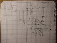
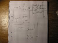
Look at the attached image, I found it on the web.

you must use the same idea as shown, specially the PRIMARY driver, 4 transistors.

And here the transformer is 1:1 or 1:1.2

Dont use the circuit that requires center tap of the primary.

Good luck
 

Attachments

  • smps_mosfet_drive_xfmr2.jpg
    smps_mosfet_drive_xfmr2.jpg
    328.3 KB · Views: 222
  • smps_mosfet_drive_xfmr.jpg
    smps_mosfet_drive_xfmr.jpg
    321.3 KB · Views: 168
Last edited:

KX36

New member
I would not recommend the GDT secondary circuit shown. I tried something very similar on my last build and found it to drive the gates very poorly. the PNP turn off transistor takes a significant amount of time to desaturate thorough the relatively high impedance of the GDT inductance making it very slow, although some of that was because it was a single ended PWM IC driving it with a coupling capacitor and a turns ratio of 1:2:2. I would recommend if possible using a GDT only with 2 output ICs, with totem pole drivers as in the diagram and without the secondary circuit.
 

demykiko

Member
Look at the attached image, I found it on the web.

you must use the same idea as shown, specially the PRIMARY driver, 4 transistors.

And here the transformer is 1:1 or 1:1.2

Dont use the circuit that requires center tap of the primary.

Good luck

Thanks again MicrosiM..so it is clear that you recommend the totem pole configuration as driver for GDT and with the use of match pair BD139 and BD140..
I will try that as soon as I get my order of those transistors..

Regards,
demykiko
 

demykiko

Member
I would not recommend the GDT secondary circuit shown. I tried something very similar on my last build and found it to drive the gates very poorly. the PNP turn off transistor takes a significant amount of time to desaturate thorough the relatively high impedance of the GDT inductance making it very slow, although some of that was because it was a single ended PWM IC driving it with a coupling capacitor and a turns ratio of 1:2:2. I would recommend if possible using a GDT only with 2 output ICs, with totem pole drivers as in the diagram and without the secondary circuit.

Thanks KX36..I think MicrosiM included that secondary circuit just in case the Power transistors to be driven are IGBT..because I always see that circuit if the power switchers are IGBT..But let's see which one will give a good result..
My experiment will be little bit delay due to the nature of my Work now plus waiting for the order of components..But I'm really excited about how that circuit will perform..I believe It's just a matter of time for me and the followers of this thread and twenglish as the starter of this thread..
 

MicrosiM

Administrator
Staff member
Thanks KX36..I think MicrosiM included that secondary circuit just in case the Power transistors to be driven are IGBT..because I always see that circuit if the power switchers are IGBT..But let's see which one will give a good result..
My experiment will be little bit delay due to the nature of my Work now plus waiting for the order of components..But I'm really excited about how that circuit will perform..I believe It's just a matter of time for me and the followers of this thread and twenglish as the starter of this thread..

Yes, I have only shown that circuit for reference.

But the secondary side transistor circuit can be modified and can be very helpful to drive MOSFETS, and you can get around 120ns raise and fall.

the modification can be made to have negative swing.


Lets see what you will get, then we discuss it further


KX36 is also 100% correct
 

demykiko

Member
I Hope you can show us sooner your working GDT plus some good clean waves and some sample of toroid that is not as big as I posted..
I really appreciate it and others too who have desire to make their own working GDT..
Your posts will serve as encouragement to us..Thanks MicrosiM for your time..
 

MicrosiM

Administrator
Staff member
I Hope you can show us sooner your working GDT plus some good clean waves and some sample of toroid that is not as big as I posted..
I really appreciate it and others too who have desire to make their own working GDT..
Your posts will serve as encouragement to us..Thanks MicrosiM for your time..

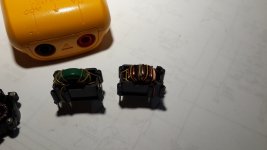
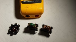
Attached is 3 GDT I am using, I will try to put some scope waves soon
 

Attachments

  • 2015-04-15 00.34.08.jpg
    2015-04-15 00.34.08.jpg
    135.3 KB · Views: 76
  • 2015-04-15 00.34.29.jpg
    2015-04-15 00.34.29.jpg
    165.1 KB · Views: 66

MicrosiM

Administrator
Staff member
Enjoy an amazing wave from the transformer, the first at your right in the picture
:D
 

Attachments

  • DS0236.BMP
    16.2 KB · Views: 156

demykiko

Member
Attached is 3 GDT I am using, I will try to put some scope waves soon

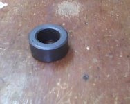
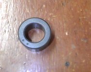
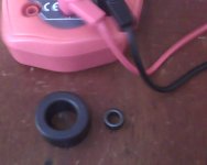
Here are the the toroids that are to be tested as soon as I obtain driver transistors for it..

at the left is the toroid which you mentioned so big, at the right is a toroid from chinese cfl so small..

two toroids.jpg

Yours are exactly fit as GDT in terms of size..It looks its size is at the middle of mine

And regarding the waves you showed, I think it is perfectly good in shape..

Hoping that I can have my complete components and time to start testing those toroids of mine..

Thanks MicrosiM for your support..
 
Top