2 kwts discreet class d need help

stewin

Member
here you are


At 70°C, the BC337 pull down R2, so you've a protection signal.

For 5V use, you've to recalculate NTC and R1 to have a Vbe (at 25°C) of about 130mV
The transistor must be an high gain NPN, such the BC337-40 (400 Hfe)

is this correct am? i on the right track?
 

Attachments

  • ucd discreet with protection v2 coloured.pdf
    65.6 KB · Views: 308
  • ucd discreet with protection v2.jpg
    ucd discreet with protection v2.jpg
    414.8 KB · Views: 198
Last edited:

pergo

New member
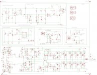
i suggest you to simplify the schematic.
My overtemp schematic don't need a comparator. You can put the collector of T5 on the 555's pin4.
Also, you can drive the relay by the 555.

I prefer to use the 555 as a "heart" of the circuit. Each protection will go on the 555, so the 555 drives the relay and the LTP's CCS.

The 555 is a delay circuit, so at start up will delay the CCS pull-down and, one second after, it power up the relay. --> the amplifier start to play music.

At shutdown, relay and CCS shut-off together, to prevent thump.

When one of the protection get ON, the 555 will shut-off by the reset pin, so the CCS goes off and the relay goes off.

It's simpler, because you remove the LM393 and some transistors.


Last thing: i suggest to use a trimmer (1k) in R19, for fine overtemp tuning.
 

pergo

New member
for speaker protection? yes, there is, it driven by the 555 in the image.
Or you mean another relay? For what?
 

stewin

Member
oops my bad pergo. i have seen it right after the 555 timer. sorry man and thanks a lot for your patience and support . i'll post the right schema btw if you have eagle here are the files
 

Attachments

  • ucd discreet with protc.zip
    137.2 KB · Views: 398
Last edited:

pergo

New member
no problem ;)
In my schema, the speaker relay turn on after the switching start-up, so any thump is i-m-p-o-s-s-i-b-l-e
The turn off is very fast for the relay in every situation (protection or amplifier shutdown).

When you will built the amplifier, sure there will be some fine tweaks at the component's value.
 

stewin

Member
now the complete full schema . :D :D
 

Attachments

  • ucd discreet with protection v2 coloured.pdf
    57.4 KB · Views: 294
  • ucd discreet with protection v2.pdf
    57 KB · Views: 276
  • ucd discreet with protection v2.jpg
    ucd discreet with protection v2.jpg
    195.2 KB · Views: 157

irvynejay

New member
Hi pergo and norazmi ,stewin can toten pole be applied on ir2110 design i need your adive how and what kind of toten pole to used can i use norazmi toten pole and how?
 

pergo

New member
in general, you can add any bjt or mosfet totem pole after the IR2110, but you need enough bootstrap capacitance if you don't want to use ad auxiliary supply for high-side.
If you've to push 4-5A for drive FETs, you need a large bootstrap capacitor and Hfe if you play with BJT totem pole.
there are integrated gate drivers like TC4420 if you want something small.
 

norazmi

diysmps Senior Member
Stewin,

To go with high power and more parallel mosfet you need triple transistor at totem pole per/side. and i suggest u do 2 aux supply each to make sure both can have enough supply and current while driving loud. More capacity bootsrap will help to stable the aux supply rails too. In class D you dont really need to add more than 3 mosfet per side, hi and lo, 3 pair is good enough and remember when u put hi rds-on mosfet and u will have little distortion at high volume and may also cause mosfet more heat than lower rds-on. Well, Stewin why not u try with +/- 50 vdc with full bridge? :D . U need to prepared for the good PSU with many caps bank with it :D

p/s - i just getting well from FLU now i`m feel good :D

Regards.
 

stewin

Member
nice to know you are well. i have a flu too due too heavy rains and cold weather . pls draw the schema you are saying about multiple totem pole transistors. to drive the fets.
 

norazmi

diysmps Senior Member
oh same here, rains coming almost at end evening. Like u draw last schema, u put 2 2n5401 and 2 sn5551, now u just add one more, 3 2n5401 and 3 2n5551 per side. Thats it :D , and add dual aux supply with good bootsrap caps. I did 3.3k ohm feed with 15v zener diode, so i dont face aux supply problem. Full bridge of this ucd will give u massive power of audio. Keep ur mosfet by using irfp250N and dont go more for rds-on u will hurt the amp :D . Lower is better. Keep duty cycle at optimum and dont lower it too much or mosfet will suffer :p .
 

norazmi

diysmps Senior Member
irvy, ir2110 is same application like irs2092 totem pole driver. and yes u can use like what we did here to the ir2110. Watch to the gate resistor, and you need to add totem pole after the gate resistor like what we did here since u want drive high rds-on mosfet such as irf640. add totem pole and apply 4.7 ohm gate resistor after that. before totem pole u need add 22 ohm resistor too. Unless u have irfb4227 then u can avoid 22 ohm gate resistor before totem pole, and after that u can use 4.7 ohm like usual.
 

irvynejay

New member
ir2110 with btj toton pole

Could this work pls need your help and advice
 

Attachments

  • ir2110btj toten pole.JPG
    ir2110btj toten pole.JPG
    48.2 KB · Views: 307

stewin

Member
it will work but . the value of resistors ,transistors nozrami and pergo can tell you the values because it involves alot of calculations ,simulation and experience.
 

norazmi

diysmps Senior Member
Irvy gate resistor is wrong. 22 ohm first then after totem pole followed by 4.7 ohm, well... i`ll simulate it today for confirmation. Another project? :D .
 
Top