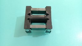
1000w smps based on LUDO3232

Silvio

Well-known member
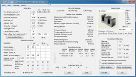
In post 57 calculation is for ETD49 transformer and not EE55. For EE55 turns are different.
IF you want turns for EE55 please give me more information, Ex Half bridge , full bridge, Purpose of use of smps ex amplifier etc
1) core material
2) frequency of operation
3) bobbin length
4) window width between bobbin and core
5) what mosfet are you using
6) Input AC voltage
7) Output PEAK DC voltage
8) what output diode used
 
Last edited:

nazirdigi

New member
150v 8 A ee55 core smps.jpg
thanks for the reply silvio.
mosfet irfp460.
mur1560 diode
ac input 220v
output peak 150vdc
is it primary and secondary twisted wires or only primary twisted.?
 

Silvio

Well-known member
Hello Nazirdigi,
I see you have already worked out your calculation with Excellent IT and you got your results. I was asking for the bobbin length which I don't have. I cannot say what fits better. I see also a mistake in your wire diameter being 2.5mm this wire is not suitable for the frequency chosen. in fact the software adjusted for you and chosen 0.5mm. This is due to the wire skin dept cannot go more than that with the frequency chosen (70Khz)

Choosing half bridge topology for this power is not a good choice either and the current amplitude in the primary will be very high (20A) I think full bridge topology will be a better choice for you for 2KW. (Half bridge is only suitable up to 1KW)

The mosfets will not make it at full power and are likely to blow due to heat build up as the rating of 20A only holds true for a heatsink temp of 25 deg. As temp grows the amp rating will go down and even the RDS ON will also go higher. You will never use the fets at full rating as they will not last very long. As a rule of thumb for continuous rating you divide the full rating by 4 and for audio you divide by 3 ( so for a 10A rated fet you get around 2.5 to 3A for continuous rating and roughly 4 to 5A for audio purpose) If you need more power you can parallel fets together so they share the power.

Regarding if the wires are twisted or side by side is your choice and you have to see how they fit in the bobbin. As a rule of thumb for a good transformer it is best to try to fit each winding in one layer (Ex half primary 1 layer, half secondary 1 layer etc) This only holds true if it is possible. Good transformer construction is the key for a good smps.

I suggest you see the 2 blog posts that I posted on this website regarding Transformer winding practices and also making litz wire at home. You will get a good idea how to fit your windings and also what material you should use for a safe transformer. A video on youtube is also available called winding small transformer for smps by Silvio, You will take a good idea what to do during the trafo wind.

Regards Silvio
 
Last edited:

nazirdigi

New member
how is this smps silvio?
 

Attachments

  • AC-DC-converter-SG3525-Full-Bridge-with-SMPS-with-TL494(1).jpg
    AC-DC-converter-SG3525-Full-Bridge-with-SMPS-with-TL494(1).jpg
    19.2 KB · Views: 261
  • Full.jpg
    Full.jpg
    21.6 KB · Views: 178
  • IR2110 - 7.jpg
    IR2110 - 7.jpg
    20.9 KB · Views: 138
  • Snap2.jpg
    Snap2.jpg
    125.9 KB · Views: 114
  • Untitled1.jpg
    Untitled1.jpg
    20.9 KB · Views: 125
  • Circuit Wizard - 13.8 Full.pdf
    178.5 KB · Views: 272
  • FULL BID TOP1.pdf
    186.8 KB · Views: 245
  • full bridge.pdf
    36.6 KB · Views: 229

Silvio

Well-known member
Hello Nazirdigi,

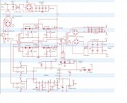
I cannot see the schematic properly as the file is too small and when I enlarge it becomes blurred.

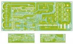
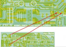
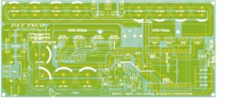
As far as I could see from the pcb layout I am assuming that you are using the one with the EE55 trafo. Well I could not see enough spacing between primary and secondary traces. The spacing should be around 3 to 4mm between these traces. Getting to the AC input side and DC bus spacing is not enough also. At least keep 3mm here in all places and even between capacitor legs. Humidity may cause it to arc

I am not sure if you are going to have feedback as I cannot see schematic.
In case that the smps is not regulated then check your peak voltage on Exellent IT. You can move the mouse on the 3 output voltages stating min V, Rated V and Max V There you will see the peak voltages of every winding. I am saying this because with the calculations you posted the peak voltages where higher than 150v
Regarding input and output capacitance I think you are Ok here. Input around 1uF per watt As for the output caps well see that they are low ESR type as they have to filter out all the ripple and having only 2000uF per rail are a bit on the low side. I do not see an output inductor either.

The pin header carrying oscillator and drivers is a good idea to keep traces away from high current paths and also short. This will also save space.

Regarding the Trafo wind give me the bobbin length and also the window space between bobbin and core and I try to work out what best to use. Please also note that if you are using a switching frequency of 70Khz then not more than 0.5mm wire can be used. You have to make several wires in parallel or twisted to have adequate current handling.

Regards Silvio
 

Silvio

Well-known member
@ full bridge circuit,

About the full bridge circuit I do not have one that I have tested yet but I am going to experiment with an offline push pull circuit smps for audio in the future and see it it works.

Silvio
 

behrad

Member
hi
i modified pcb for use mur1560 instead RURP820
also i removed output inductors.is this problem?
(my ampli box has not enough space for this smps.so I was forced remove inductors)

silvio smps.jpg
now pcb size is 23*14

mr silvio.why i can not to send pm to u and everyone?::SD
 

Silvio

Well-known member
@Behrad,
The only problem you might face without the output inductors is that at start up the smps faces a dead short while charging the secondary caps. I know there is the soft start but I faced the problem due to that my auxiliary supply had a small delay before it gives power to the circuitry and due to this the main bulk caps where fully charged.

In Ludo's smps the aux supply gave power instantly on start up and current was limited through the 50 ohm input resistor. however this compensated for the inrush current during soft start of the smps and it limited the current also during the charging of the secondary caps. in fact he did without the output inductors.

It also may be the case that when you have a surge in the output the over current protection may trip without output inductors, these serve also as current limiters. In that case you have to dump a little the over current protection. We will leave this for after you do your initial tests and see your results first.

Regarding the output diodes they are a good choice.

Regarding the PM its not working at the moment and the administrator is taking care of it.

Do not hesitate to send your messages here, other members can also learn from your questions.

Regards

Silvio
 

behrad

Member
thanks mr silvio for answer
how much noise in this smps?
is proper for audio work?
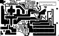
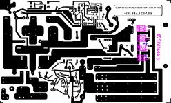
i draw new output diods in bottom pic
i used adobe photoshop so my pic is not beauty:D
point A should be connected to point B from wire in bottom pcb
also i removed 2led in output rails
silvio smps.jpg
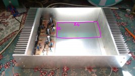
bottom pic shows my ampli box(my stereo amplis are apex a23)
smps will be placed in pink line

IMG_20171023_114551.jpg
 

Silvio

Well-known member
@Behrad
In hard switching smps the noise is not very low and the more power the more noise there is. Suppressing it is not that difficult in this smps because it runs at full duty cycle. Output inductor also filters a bit of high frequency noise in the output, however we are using a lot of capacitance so its not really needed. Ludo only used 3000 per rail on the output thus we are using 4000. Regarding input capacitance I have a value a bit more than ludo had as he was using split capacitors on the input and had 2000uf by 200v in series with another 2000uf by 200v . These being in series bring a total capacitance of 1000uf across the 310 volt rail. I have 2 X 680uf by 400v in parallel and that brings a total of 1360uF. I used 2 X 2.5uF film caps to divide the voltage. As a rule of thumb we use 1uf per watt in the input for audio.

I also suggest that you add either 2 film caps of 1uf across pos and center ground and one on neg and center ground, or you can use one of 0.47uf across + and - on the output. This will filter a lot of noise as well.

I do not know how much space left you have but I suggest that you make a metal divider between the amp and the smps to screen out any noise. As far as the indicator Led (green) you can use the one near the oscillator board instead, this will only indicate that the auxiliary supply is on. The red one indicates the overload when on

May I ask what is the space left in the box is used for? I do not think you need more capacitors, this is not like an iron trafo smps runs at much higher frequency and fills back up the capacitor bank 1200 times faster compared to iron trafo running at 50Hz I am saying this because you can turn around your smps as there is ample space left and not leaving it so cramped with the amplifier board.

Regards Silvio
 

behrad

Member
i will use 2*0.47nf 250v in parallel to output rails and install them in bottom board sure
also i will try enhanced input capacity to 2000uf and use aluminium sheet all round smps(now i have enough space in box)
total empty space in my amp box is 24cm*30cm
i will use 15*24 for this smps and 15*24 for preamplifier circuit and another amp(subwoofer ampli:adoration:)
mr silvio.i have regulator power supply circuit that i used it to iron trafo
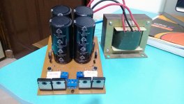
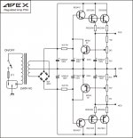
this is psu5 from apex that has 4*18000uf 71v
when i used psu5 to my amp i did not have any noise in speaker
can i use psu5 to this smps?
bottom pics is my psu5 and its schematic:

IMAG0057.jpg
1500833206_apex-regulated-psu-10-vyhodnaya-versiya-dlya-relsov-55v-90v.jpg

respectfully
 
Last edited:

Silvio

Well-known member
@Behrad,
You only need 1uF at each rail tied to center ground. You could find a couple of film caps from old ATX psus used for computers.

I suggest you should try it out without any added caps at the output first. Adding more caps will bring the need for a second stage soft start for sure to charge the extra caps added. Your over current protection will trip without it.

I do not remember what output voltage you are going to have in the smps. This need not be regulated for audio. However the peak voltage must not exceed the maximum rating of your amplifier. Please also remember that the output voltage will sag a little with load due to the smps is not regulated. Without output inductors will be in the region of 10 to 15%.

Regarding the noise it will not be audible due to the smps runs at a frequency much higher than the audio spectrum this being around 60Khz which the human ear cannot hear. The response of the amp is usually up to 20Khz and will not be able to amplify any noise at that frequency.
 

behrad

Member
maximum input voltage for my amplis is +/-55v dc for 8ohm load
but my load speaker is 4ohm and for 4ohm maximum voltage is 51-52v
i read ur winding core instruction several time and realized quite well
in first i will make this smps without add any capacitor in input and output smps
if i saw noise it so add capacitors
mr silvio.can i use polyster capacitor instead film cap?
yes audible range for human is 20hertz-20kh(for most of the people is 18kh max like me-))and noise in 60kh not important because not audible for nobody
in first i decided to make ludo smps because i did not have enough space in my old box even i was asking several question in ludo tread
but i changed ampli box only for this smps and now have new amp box with enough space
ur smps is newer and i think its better from ludo and more important u are here(as circuit designer) and answer my questions very well
finally i started make this smps in next week and i will ask many questions from u;)
respectfully
 

Silvio

Well-known member
@Behrad
Regarding psu5 I see it is a nice psu and has a rather powerful punch and also being regulated. I think you will not be needing this with the smps. You will still have a good punch without it.

If you want 50-0-50 volts its no problem but that will be the peak and I think 55v will only be at the peak input voltage of 245v.
I need to know what core are you using and also the core material (Ex N87, 3c90 etc) so that I will make winding calculations for you.

Do not forget you have to add an input filter at the mains as this is not included it the smps. I am including Ludo's video so that you can see how the smps behave with the amplifier.

https://www.youtube.com/watch?v=XuBwE6fqU6A

This is my smps on the first load test. You can see a bit of voltage drop in the output due to the large output inductors being around 20uH each. I later reduced them to 1.5uH each and had better voltage stability at the output. If you calculated it in percentage the voltage drop at 50v output in your case it will be around half of what I had due to that my maximum output voltage without load was about 85v or so. in your case at 55v out at 10% drop will be 50v at best.

The over current trip was rather too sensitive at the time I did the video and later I adjusted it.

https://www.youtube.com/watch?v=18l-plvqkdU

Regards Silvio
 

behrad

Member
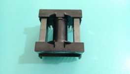
i have one etd49 but i do not know what its core is
How should i understand what is core material?
IMAG0032.jpgIMAG0031.jpg
ok i will use input line filter sure
i saw ur smps and ludo smps videos
thanks
 
Top