1000w smps based on LUDO3232

Silvio

Well-known member
@Behrad,
The core material make a difference in the number of turns and this can vary between 18 and 22 turns for the primary. In that case if you have no means to know the core material of the trafo you bought then I have to keep a safe margin for you and go in the middle. You can always ask the seller you bought it from maybe he can tell you.
 

Abet

New member
Hello Silvio!
It seems PM box is not working at the moment so I had to post my question here. I noticed in my build (Detex clone smps) the gdt seems to be heating up noticeably after about 30mins of use. Not too hot but is too warm to the touch. Is this normal?

Apologies for being off topic.

Albert
 

Silvio

Well-known member
@Abet
Normally ferrite cores get a little hot in operation. If you want to make a self judgment remember this. Anything that is hotter than your finger is felt warm (37 deg) If things get hotter than 45 to 50 degrees then you will feel it burning your finger, at 60 degrees it will be intolerable after 5 to 10 sec depending on how much thick is the skin on your finger. Keep this in mind that till 60 degrees it is still normal for a ferrite core but not more than 100 degrees. ( all degrees mentioned are in Celcius )

I hope that helps

Silvio
 

behrad

Member
mr silvio
please give me latest file of ur smps circuit
i have several schematic from this smps that value of the some parts is different relative to each other
i got confused:confused:
is needed i install snubber parts on board?
 
Last edited:

Silvio

Well-known member
@Behrad
you can try without snubber first and test smps. you have to install if you have ringing on the waveform across trafo
Do you have oscilloscope?
For different values I will help you out to correct them ok Just tell me which ones are they.

You will be needing 0.5mm copper wire to make windings on transformer.


Silvio
 
Last edited:

Abet

New member
@Abet
Normally ferrite cores get a little hot in operation. If you want to make a self judgment remember this. Anything that is hotter than your finger is felt warm (37 deg) If things get hotter than 45 to 50 degrees then you will feel it burning your finger, at 60 degrees it will be intolerable after 5 to 10 sec depending on how much thick is the skin on your finger. Keep this in mind that till 60 degrees it is still normal for a ferrite core but not more than 100 degrees. ( all degrees mentioned are in Celcius )

I hope that helps

Silvio

Great info, thank you! I am making sure that I am not pushing the core into saturation during operation.

Regards,
Alber
 

behrad

Member
@Behrad
you can try without snubber first and test smps. you have to install if you have ringing on the waveform across trafo
Do you have oscilloscope?
For different values I will help you out to correct them ok Just tell me which ones are they.

You will be needing 0.5mm copper wire to make windings on transformer.33.jpg


Silvio
unfortunately i do not have oscilloscope
For example, in the pictures below
33.jpg
222.jpg
in some schematics little switching power is 12v but in another schematic is 15v
or marked resistors in some schematic is 22k but in another is 18k
which one is correct?
 

Silvio

Well-known member
unfortunately i do not have oscilloscope
For example, in the pictures below
View attachment 6432
View attachment 6431
in some schematics little switching power is 12v but in another schematic is 15v
or marked resistors in some schematic is 22k but in another is 18k
which one is correct?

Ok for the bleeder resistors 18K get hot so change to 22k 3watts
For aux supply power 15v to 18v is better than 12v. (preferably regulated) I had 12 volts supply in the beginning but altered zener and bring it up to 15v.
If you are to use unregulated option like schematic the output inductors need not be more than 1.5 to 2 uH. (10mm dia ferrite rod 30mm long with 6.5 turns 1.5mm dia copper wire)
Resistors for current transformer R1 & R2 make 22 ohms 2w metal film.

Regards Silvio
 
Last edited:

behrad

Member
For aux supply i did not find 15 or 18 volt smps adaptor in my local city
But i find 24v/1a
Can i use it without any problem?
 

Silvio

Well-known member
mr silvio
relay 12v/8a is double or single?

I used a double one because that I had in my junk box. If you have a single contact relay it will do the job just the same as long as it can handle the current in the input (5-6 Amps)
 

Silvio

Well-known member
For aux supply i did not find 15 or 18 volt smps adaptor in my local city
But i find 24v/1a
Can i use it without any problem?

For the auxiliary supply power up to 300-500 mA is enough. For the voltage I think 24v will be too much so 12v will have to do. If you want you can make a simple small psu if you have a 14vac trafo from an old radio or something else. It will only need a small bridge and a smoothing capacitor followed by a 7815 IC regulator. Anyway I leave that to your choice.
 

behrad

Member
i find 2 mistake in ur schematic
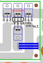
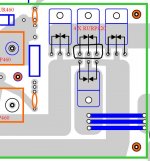
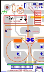
1)in one schematic middle output di
ode pins is connected to top but in another schematic not connected to top line
which one is right?
5.jpg4.jpg
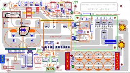
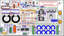
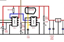
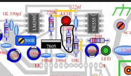
2)also r14 resistor in schematic is 10k but in pcb is 220ohm
33.jpg222.jpg
for auxillary power smps output negative line is connected to input negative line?is this correct????
89.jpg
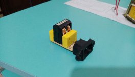
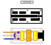
also in first i made input line filter
the parts are one input line inductor+470nf and 330nf 275volts caps
is this enough?
IMAG0058.jpg
 
Last edited:

Silvio

Well-known member
BUG fix

1) Diode bridge the pic on the right is the right one. (the middle diodes should not be touching the top trace)

2 R14 is 10K ohm in the component layout the color is correct but the value written is wrong. It should be 10K

3) Your markings are correct, where marked IN is the positive bus supply 310vdc. Note both auxiliary and smps share a common ground. (12v auxiliary negative is connected to the bus negative) This is correct as both share a common ground

4) The input filter is ok but if you use same value caps at both ends it will work better

emi filter.JPG

5) The filter inductor must carry the full load so a 5 amps rating is needed. I cannot see wire size but some self judgment from your end will let you know.

regards Silvio
 

Silvio

Well-known member
The final results for the 1000w smps

Trafo ETD 49 N87 Material Maximum output voltage 80-0-80 at 242vac Auxiliary voltages 15v-0-15v @ 500mA

New winding turns Primary 18 turns Secondary 9-0-9 turns Ratio 1:1 Bmax 1600g

Ampere turns Primary 2 bundles of 4 wires 0.5mm dia twisted Secondary 2 bundles of 4 wires 0.5mm twisted

Current density 6 amps per mm² (2 bundles as above cross sectional area 1.57mm²)

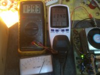
Total power absorbed 1216W Total power input 1383W Efficiency 87.9%
Input voltage 233v output voltage 143vdc

Temperature Readings at an ambient temperature of 16 deg C

Result after 1 hour of operation No Fan used

input ACV 237 output voltage 158v load 60watts

core temp =32 deg
copper temp =35 deg
input bridge= 32 deg
heatsink = 30 deg
SG3525 =35 deg
IR2110 =38 deg

Continued test with more load No fan used for further 15 min


Input voltage 230vac output voltage 144vdc load 749 watts

core temp =32 deg
copper temp =36 deg
input bridge= 65 deg
heatsink = 52 deg
SG3525 =37 deg
IR2110 =40 deg

Continued test with more load and FAN ON for further 15 min

Input voltage 229vac output voltage 138v load 938 watts

core temp =35 deg
copper temp =38 deg
input bridge = 74 deg
heatsink = 26 deg
SG3525 =27 deg
IR2110 =29 deg

IMG_0909.JPG

SMPS at 1170 watts
 
Last edited:

Silvio

Well-known member
Thank you MicrosiM, If it was not for this website and all those who contributed with good answers to others on various treads that I read, I would not have been able to produce this smps. I learnt a lot of things about power electronics and also how to make safe transformers and pcbs. I hope I will be able to contribute the same way as I benefit from this website.

Regards Silvio
 
Top