12v 250w Car SMPS based off SG3525

wally7856

New member
This is an official update of the transformer primary calculation constant list.

Np = (Vmax * 10 ^ 8) / (X * F * B * Ae)

Np = Number of primary turns

The constant X used in the primary turns formula can be any of the following.

1.11 - compensates for the sine wave ratio of RMS to average voltage. This constant is not used by itself.

1 - Used for half wave, square wave operation of a transformer. A flyback converter uses this constant. Also a one and two transistor forward converter. The hysteresis curve (flux swing) only uses one quadrant.

2 - This is the square wave constant above multiplied by 2. there are two semi cycles in each full cycle (Hertz refers to full cycles). An Interleaved forward converter (two, one transistor forward converters Interleaved together) gives two power pulses per period. The hysteresis curve (flux swing) only uses one quadrant.

4 - This is the constant 2 above multiplied by two for topographies that have a hysteresis curve (flux swing) in both quadrants, like a full bridge circuit, half bridge or push pull.

4.44- Used for standard sine wave transformer design. This is the result of the constants above.
1.11 x 2 semi cycles in each full cycle x 2 flux swing in both quadrants.

Hopefully this is correct now. I only use the 4 constant so i have verified that one many times, but i have never used the others.
 

wally7856

New member
“Two question. Imagine that I get a transformer from a faulty PSU, like I said. I take all the wire off and dismount the core and the core support.

What information I need to take from the core? Dimensions? If so, Which one? (The Area of center leg of transformer? Anything else?)”

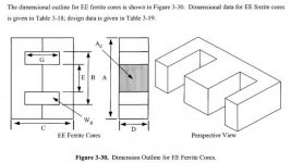
Give the dimensions for A thru H and look to see if it has a gap. Try to use a dial caliper if you can.

“About the push-pull topology, for example, as we know, we need a center tap on the primary and secondary. How that is done? In which part of your calculations you take that into account?”

Center tap means 2 winding’s. Each winding on primary must support full DC bus voltage. So the primary calculation is giving you the turns for each winding. Example answer of 10 turns means 20 turns total with center tap at 10 turns. So you need two 10 turn winding’s. The secondary calculation is also for each winding.
 

Attachments

  • E-core dimensions.pdf
    393.6 KB · Views: 152

AMSA

New member
Wally, thank you so much! I start to understand this now.

Allow me to ask you one more thing. There is a post, don't remember now where (in this forum) that you have suggested the turn for the transformer of someone. There, you said that guessing N87 material, looking to the flux chat, the 1400 Gaus (0,14T) seemed to be the best place to run the core. A let the link here: http://www.epcos.com/web/generator/...F/PDF__N87,property=Data__en.pdf;/PDF_N87.pdf (don't remember if it was from EPCOS)

My question is, what is the criteria/rule to decide which point is the most suitable to run the core? Taking the advantage of that, could you tell me in which graph you evaluate that? (in which page and which graphic?) Maybe page 4, Dynamic magnetization curves?

That is a doubt that I have for a long time. How do I know which Bmax I should take to make the calculations and why.

Another thing that I have a doubt is related to what you have told in your previous posts. That is, something like the flux swings on the four quadrants. Can you explain a little bit more?

Current density. How do we know what current density to use in our application?

In your design, you wrote:

We also know that with no output inductor we will need 1.2 times the output current.
So 1.2 x 3.57A = 4.28A, secondary current.

Why we need 1,2 times the output current?

To finish, when you have computed the Skin Depth: Skin depth in mils = 2837 / squar root of frequency in hz, you used 2837. What is this constant?

Thank you so much for taking out my doubts! I think that will help many people from this forum.

Regards.
 

AMSA

New member
I have forgotten to ask you another thing about the mils.

Wherever we see on you reference CM, you mean always circular mil. Right? I thought that cm was centimeter. Geez.
 

wally7856

New member
“Allow me to ask you one more thing. There is a post, don't remember now where (in this forum) that you have suggested the turn for the transformer of someone. There, you said that guessing N87 material, looking to the flux chat, the 1400 Gaus (0,14T) seemed to be the best place to run the core. A let the link here: http://www.epcos.com/web/generator/W...f;/PDF_N87.pdf (don't remember if it was from EPCOS)

My question is, what is the criteria/rule to decide which point is the most suitable to run the core? Taking the advantage of that, could you tell me in which graph you evaluate that? (in which page and which graphic?) Maybe page 4, Dynamic magnetization curves?”

Page 5 relative core loss verses frequency. Pick your operating frequency and as a general rule use 100KW/Meter cubed for core loss.

“That is a doubt that I have for a long time. How do I know which Bmax I should take to make the calculations and why.”

B = Flux in Gauss, common values of 1200 to 1600.

The curves show the flux verses core losses as well as a few other things. But even without those curves we can make some good guesses what the numbers are. The only numbers we can really play with is the flux density and frequency, the other numbers are fixed. As the frequency goes down you can run higher flux, but as a general rule do not exceed 1600G unless you have a very good reason to. You run the risk of saturating the core and or running in a non linear region. You can almost always run 1200G even up to 100khz if the ferrite was designed for a power transformer.

“Another thing that I have a doubt is related to what you have told in your previous posts. That is, something like the flux swings on the four quadrants. Can you explain a little bit more?”

I should have said 2 quadrants.

“Current density. How do we know what current density to use in our application?

In your design, you wrote:

We also know that with no output inductor we will need 1.2 times the output current.
So 1.2 x 3.57A = 4.28A, secondary current.

Why we need 1,2 times the output current?”

That particular topography of center tapped transformer in to a bridge and capacitor for a +- supply uses 1.2 times the transformer current for the output.

“To finish, when you have computed the Skin Depth: Skin depth in mils = 2837 / squar root of frequency in hz, you used 2837. What is this constant?”

It is a unit-less constant to make the formula come out.

And yes, cm in my post means circular mils, most awg wire charts will list this number.
 

AMSA

New member
Hi there wally and others!

Thanks once again for your reply!

About the flux chart and the Bmax that we should choose, you mean that for our applications the best suitable rule to choose the adequate Bmax is using a general rule that is 100KW/Meter cubed for core loss. In this case, just to be sure that I have understood, I have posted a picture of that example:

http://imageshack.us/photo/my-images/138/73765714.png/

Can you confirm it?

Can you give me some reference that explain the swing of the flux in the 2 quadrants?

Thank you very much again!

Best regards.
 

wally7856

New member
“About the flux chart and the Bmax that we should choose, you mean that for our applications the best suitable rule to choose the adequate Bmax is using a general rule that is 100KW/Meter cubed for core loss. In this case, just to be sure that I have understood, I have posted a picture of that example:

http://imageshack.us/photo/my-images/138/73765714.png/

Can you confirm it?”

Yes that is correct.

“Can you give me some reference that explain the swing of the flux in the 2 quadrants?”

Look in McLyman’s book chapter one for hysteresis loops (BH loop).
 

wally7856

New member
AMSA, When you try to take apart your transformer from your computer power supply, use boiling water. Many people here have said that boiling the transformer for 5 minutes will allow them to take it apart.
 

wally7856

New member
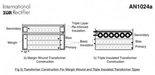
AMSA, Also, when taking the transformer apart, pay attention to the insulation at the end of the winding to the bobbin. Measure how wide the insulation is. Usually there is 6 to 8 MM of insulation then your winding’s and then 6 to 8 more MM of insulation. If there is no insulation then the transformer is wound with special triple insulated wire. Almost imposable for us to buy.
 

AMSA

New member
Hello wally, I appreciate your patience.

The boiling water is to separate both parts of the core? (I think that those parts are fixed together with some kind of epoxy glue. I read that somewhere)

Wally, about the insulation, I can't understand. You are referring to the insulation between bobbins? For example, the insulation (with tape, or whatever) between the primary to the secondary?

Taking the advantage of this my reply, I'd like to ask you another thing too. About the wire thickness.

In your calculations, when you were determining the wire size AWG, you considered the wire insulation? I ask this because when we are doing the wire fit, we need to take into account the thickness of the wire insulation, right? I have not seen you taking into account the insulation thickness. Maybe I am wrong. I'll read again that part.

To finish, When we buy some wire of a specific AWG, that wire diameter doesn't count with the insulation, right? For example, say we buy a 23 AWG, which corresponds to 0,25815 mm square. That wire size doesn't count with the thickness of the insulation, right? How can we know the thickness of the insulation? That varies from manufacturer to manufacturer?

Regards!
 

wally7856

New member
“The boiling water is to separate both parts of the core? (I think that those parts are fixed together with some kind of epoxy glue. I read that somewhere)”

Yes

“Wally, about the insulation, I can't understand. You are referring to the insulation between bobbins? For example, the insulation (with tape, or whatever) between the primary to the secondary?”

Look at picture.

“In your calculations, when you were determining the wire size AWG, you considered the wire insulation? I ask this because when we are doing the wire fit, we need to take into account the thickness of the wire insulation, right? I have not seen you taking into account the insulation thickness. Maybe I am wrong. I'll read again that part.”

In the beginning of the post i forgot about insulation thickness then i said look on Ebay for magnet wire and you can find wire with thickness listed.

“To finish, When we buy some wire of a specific AWG, that wire diameter doesn't count with the insulation, right? For example, say we buy a 23 AWG, which corresponds to 0,25815 mm square. That wire size doesn't count with the thickness of the insulation, right? How can we know the thickness of the insulation? That varies from manufacturer to manufacturer?”

The awg is only the bare wire size. For magnet wire for transformers it is best to know what wire you are buying and look up the spec. Here is an example for 20awg double heavy magnet wire.

http://www.ebay.com/itm/20-AWG-Gaug...498?pt=LH_DefaultDomain_0&hash=item3a732b6b32

or search for

20 AWG Gauge Enameled Copper Magnet Wire 200C 2oz 39ft Magnetic Coil Winding
 

Attachments

  • vde ir app note.jpg
    vde ir app note.jpg
    20.1 KB · Views: 77

AMSA

New member
Hi wally, I see what you mean.

There is a problem regarding the wire. I'm in Europe, and I have tried to find in the ebay.co.uk that particular type of wire that you have suggest through the ebay.com link and I couldn't find. Do you have any other suggestion regarding the type of the wire? (Maybe I didn't searched as I should)

Another question Wally. In McLyman's book and another one that I have read, they start to do the calculations in order to select the appropriated core. In your calculations you haven't done that. I think. The "reference/methodology that you adopt is to measure the Ae, that is, the area of the center leg. Right? I don't if I have explained myself well.

I am right now specifying my Foward converter in order to start doing the transfomer.

AH! About the transformer, tomorrow I'll give you the size of the core that I have told. The core that I have taken from a ATX power supplie (I think).

Regards.
 

wally7856

New member
“There is a problem regarding the wire. I'm in Europe, and I have tried to find in the ebay.co.uk that particular type of wire that you have suggest through the ebay.com link and I couldn't find. Do you have any other suggestion regarding the type of the wire? (Maybe I didn't searched as I should)”

Every electronics store sells magnet wire. It is very common.

“Another question Wally. In McLyman's book and another one that I have read, they start to do the calculations in order to select the appropriated core. In your calculations you haven't done that. I think. The "reference/methodology that you adopt is to measure the Ae, that is, the area of the center leg. Right? I don't if I have explained myself well.”

Like i said before. Buying transformer cores is difficult. When i find a core i can buy, i calculate the Ap (area product) and look in Pressman’s book to see how many watts it can take. The Ap = the window area in CM squared x the area of the center leg of the E core in CM squared. This gives us the Ap also called WaAc. In Pressman’s book Chapter 7 page 307 to 312 he has charts for different topologies, frequency, and WaAe and shows how many watts each one can take. There will be such a few number of cores you can buy you will only have to calculate the WaAc maybe 6 times and everything you want to build will have to be made with those cores.


“I am right now specifying my Foward converter in order to start doing the transfomer.

AH! About the transformer, tomorrow I'll give you the size of the core that I have told. The core that I have taken from a ATX power supplie (I think).”

Good i am very interested in how it is constructed and how big it is. Do not forget to try to identify the driving topology, probably half bridge or 2 transistor forward.
 

Attachments

  • Window area drawing Capture.jpg
    Window area drawing Capture.jpg
    20.6 KB · Views: 68

AMSA

New member
I wally,

Thanks so much for your reply.

I see. That method that you have mentioned it makes sense. It really makes lot's of sense (since buying transformer cores is difficult).

Regarding the wire, I will make a call to one or two electronics store next to me in order to know if they have that kind of wire. However, I have some different sizes of wire, but I don't know if they are magnet. Those wires were given to me in the pat by s a colleague and from other transformers that I have tried to open. But in any case, if I use that wire, we don't know the bare size of the wire, only the total wire size with the insulation, right? (I might have 5 or 6 types os wire size! I'll post here the size later).

About the converter topology, I was thinking on a single MOSFET forward converter.

BTW, if doing with 2 transistor forward, there is no need the reset winding, right?

Regards!
 
Last edited:

AMSA

New member
Hi again wally. I have forgotten to ask you another thing.

You said that the best way to select the core is calculate the Ap (area product). The Ap is computed like the window area in centimeters squared x area of the center leg of the core (E core) in centimeter squared, that is: Ap = Aw x Ae (see the attached)


So, according to your last attached, that means that for calculating the Aw, we do: Aw = G x [ ( B - E )/2 ].
For Ae = D x E.

Is this right?

If so, let me ask you another thing. In the next attach we have a core dimensions and some data:


The Ae that this datasheet presents is the core magnetic cross-section area? If so, my calculations gives 185mm squared instead of 178mm squared. Like in datasheet. What I am doing wrong?

To finish, in the ETD core we must calculate the core magnetic cross-section area using the circle formula?

Regards.
 

codex653

New member
oh wow! I can see this thread has really had a lot of action to it since i've been gone! :eek:
I've had so little time that I have been unable to get to redoing this transformer. First night after classes and I had many hours of reading/homework ((@ oh well, whats new haha.

Anyways, I hope AMSA can get your transformer to work properly. I'm interested to see how it turns out. Good Luck!
 

AMSA

New member

wally7856

New member
“About the converter topology, I was thinking on a single MOSFET forward converter.”

Well it looks simple, but i have never actually seen anyone make one. It would take a little studding to figure out the reset winding. Also finding example schematics may be hard to find.

“BTW, if doing with 2 transistor forward, there is no need the reset winding, right?”

That is correct.
 

wally7856

New member
“You said that the best way to select the core is calculate the Ap (area product). The Ap is computed like the window area in centimeters squared x area of the center leg of the core (E core) in centimeter squared, that is: Ap = Aw x Ae (see the attached)”

The jpg you made showing Aw Ae is wrong. The Ae is the middle leg of the Ecore. The end leg of an Ecore is 1/2 the area of the center leg.

So, according to your last attached, that means that for calculating the Aw, we do: Aw = G x [ ( B - E )/2 ].
For Ae = D x E.

Is this right?”

Your formula is correct except for typo with Aw with Wa. Wa = window area.

“If so, let me ask you another thing. In the next attach we have a core dimensions and some data:

The Ae that this datasheet presents is the core magnetic cross-section area? If so, my calculations gives 185mm squared instead of 178mm squared. Like in datasheet. What I am doing wrong?”

If you take the minimum dimensions 1.46 CM x 1.17 CM = 1.71 CM squared.
If you use the average dimensions 1.49 CM x 1.195 CM = 1.78 CM squared.


“To finish, in the ETD core we must calculate the core magnetic cross-section area using the circle formula?”

Yes. But calculating the window area will be harder because the legs are semi circle. Look in McLyman’s book on page 127. He has all the ETD core sizes calculated out.
 

wally7856

New member
Codex653 said “I've had so little time that I have been unable to get to redoing this transformer. First night after classes and I had many hours of reading/homework”

You have other fish to fry now. When the time is right then come back to your smps design.
 
Top