undrtkr
New member
hi all 
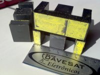
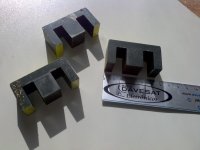
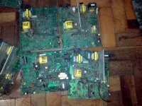
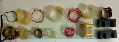
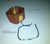
i've been colecting some parts to make a SMPS for my UCD amplifiers, and on the past days i got the crucial part for start the project, some E cores from big old smps boards that a friend gave me
i'm thinking on half bridge with +-80v and 10~15 amps output to supply the UCDs, and reading the forum i liked so much Ludo's topic and his smps, maybe it will be my starting point
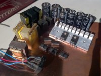
i already have almost all the parts for making the smps, just need to buy output capacitors, wire for transformer, another small parts and make the PCB, i'll list the parts that i have and possible doubt about each one:
IR2110 and KA3525A think no problem here, is this KA3525A the same SG3525?
GBPC2506 rectifier for AC input, think no problem here
2x 1200uf/200v and 4x 820uf/200v caps for input, can i use all these capacitors together?
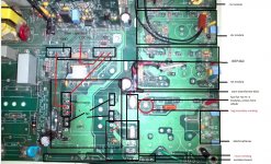
IRFP460A, you can see on the pictures there are a small ferrites on source legs of IRFPs, how about that?
BYV42E-200 diodes for output, the datasheet says 30A/200V, 15A per leg ultrafast rugged diodes, even the pinout don't let me use the 2 diodes of package on negative rail, can i still use it like a 15A diode at least?
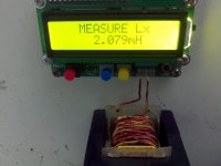
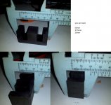
the core is E55/28/21 from N67 material, 3,54cm2 of Ae, by the size i can imagine this core can provide a lot of watts, but i don't know about this material, anyone have faced N67 before?
my final questions are:
how many watts can i get with this core and IRFP460A?
can i build Ludo's smps using these parts with no problem? (i know that i have to recalculate the turns for my core)
anyone knows an alternative for MUR460? i have some MURHF860 8A/600v it's like 2x MUR460 on same package, so can i use MURHF860 instead MUR460?
that's all for now, i'll be attaching some pictures and datasheets
all kind of help and comentary are welcome
thank you all
i've been colecting some parts to make a SMPS for my UCD amplifiers, and on the past days i got the crucial part for start the project, some E cores from big old smps boards that a friend gave me
i'm thinking on half bridge with +-80v and 10~15 amps output to supply the UCDs, and reading the forum i liked so much Ludo's topic and his smps, maybe it will be my starting point
i already have almost all the parts for making the smps, just need to buy output capacitors, wire for transformer, another small parts and make the PCB, i'll list the parts that i have and possible doubt about each one:
IR2110 and KA3525A think no problem here, is this KA3525A the same SG3525?
GBPC2506 rectifier for AC input, think no problem here
2x 1200uf/200v and 4x 820uf/200v caps for input, can i use all these capacitors together?
IRFP460A, you can see on the pictures there are a small ferrites on source legs of IRFPs, how about that?
BYV42E-200 diodes for output, the datasheet says 30A/200V, 15A per leg ultrafast rugged diodes, even the pinout don't let me use the 2 diodes of package on negative rail, can i still use it like a 15A diode at least?
the core is E55/28/21 from N67 material, 3,54cm2 of Ae, by the size i can imagine this core can provide a lot of watts, but i don't know about this material, anyone have faced N67 before?
my final questions are:
how many watts can i get with this core and IRFP460A?
can i build Ludo's smps using these parts with no problem? (i know that i have to recalculate the turns for my core)
anyone knows an alternative for MUR460? i have some MURHF860 8A/600v it's like 2x MUR460 on same package, so can i use MURHF860 instead MUR460?
that's all for now, i'll be attaching some pictures and datasheets
all kind of help and comentary are welcome
thank you all