You are using an out of date browser. It may not display this or other websites correctly.
You should upgrade or use an alternative browser.
You should upgrade or use an alternative browser.
1kw or more new SMPS project, help with parts
- Thread starter undrtkr
- Start date
undrtkr
New member
i'm using paint and ctrl+c ctrl+v hehe
attached the picture you asked, the wire diameter is 4mm
note the wires don't come from bobbin, it will go direct to PCB, on red point that i've marked on last post picture, and output gnd
attached the picture you asked, the wire diameter is 4mm
note the wires don't come from bobbin, it will go direct to PCB, on red point that i've marked on last post picture, and output gnd
Attachments
-
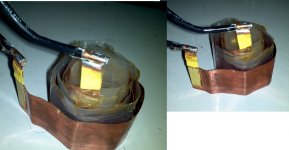 secundary.jpg269 KB · Views: 61
Last edited:
If the 820uF caps are in parallel then they are the PFC bulk capacitor’s. You still need to split the bulk voltage (385vdc) in 2 by forming a voltage divider with caps. I think i see how they are doing it. Look at your PCB at the caps C6 and C7, those caps look like high power AC caps. See if they are in series and connect to the transformer primary. If those are the right caps we will need them for your build.
undrtkr
New member
"If the 820uF caps are in parallel then they are the PFC bulk capacitor’s. You still need to split the bulk voltage (385vdc) in 2 by forming a voltage divider with caps. I think i see how they are doing it. Look at your PCB at the caps C6 and C7, those caps look like high power AC caps. See if they are in series and connect to the transformer primary. If those are the right caps we will need them for your build."
these capacitores are 0.47uF 250Vac in parallel with input inductors, this part of board is the AC in filter i think
you can follow the red tracks that i've drawn on picture interligating the primarys fets and the PFC bulk capacitors that dont appears on picture
i think this smps don't uses half-bridge, because don't have a voltage divider, no floating capacitor at primarys, and no more parts common to half bridge
the primary fets and pfc bulk capacitors are connected directly
Last edited:
“you can follow the red tracks that i've drawn on picture interligating the primarys fets and the PFC bulk capacitors that dont appears on picture”
If you did not make a mistake tracing the wires then it can not be a half bridge. It could be a 2 transistor forward converter except the math no longer works for the transformer. You would have 385vdc in and it would not be divided by 2, you would then need 40 turns not 20 for the primary.
Please retrace the circuit and look at this schematic and see if it matches up. Hint follow the diodes also.
Attachments
-
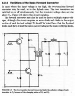 forward converter.JPG103.9 KB · Views: 42
“how now? everything changes, why 10 turns on primarys?”
Your diagram shows the 2-10turn primary’s in series for a total primary of 20 turns. But you have just confirmed that this is a 2 transistor forward converter with 385vdc in. The math for calculating transformer turns no longer works out.
Ae 3.54, 1250G, 70khz, 385v = 31.07 pri turns.
There must be something more going on with that PCB. I do not think we should spend any more time trying to figure it out. We know what we have to do to build a half bridge. I think we should move on to transformer design for your half bridge.
undrtkr
New member
yes i agree with you, but this board is a strange piece of art for me haha
hope the notes that i've take about the construction of this transformer give you some knowledgment
ok, can you look at this post
http://www.diysmps.com/forums/showt...ct-help-with-parts&p=6221&viewfull=1#post6221
and give some reply about my calculations, and the circuit?
thank you
hope the notes that i've take about the construction of this transformer give you some knowledgment
ok, can you look at this post
http://www.diysmps.com/forums/showt...ct-help-with-parts&p=6221&viewfull=1#post6221
and give some reply about my calculations, and the circuit?
thank you
I saw your earlier calculations and your choice of 1200 Gauss is a good one, but lets start over.
The international voltage range is 85-265vac 50/60hz. You have to make a decision on if you want to use this or a smaller range just for your area. If you go international everything gets a little harder, more turns on secondary, higher primary current rating, more bulk input capacitance. Pick a range let us know what you picked and make your calculations. If you show your work then we can look for mistakes.
Also you must decide on the safety margins for the winding’s. Did you notice that the tape on your transformer bobbin was 33mm wide and the widest winding was 24mm wide. 33mm - 24mm = 9mm / 2 = 8.5mm. I think the strictest VDE spec is 8mm per side. You can go less, about half of this with a lower safety rating. My opinion is shoot for the 8mm per side and if you need just a mm or so more then take it.
You might get lucky and pick a good frequency to start with but remember frequency changes the number of winding’s as does the Gauss and you can vary both of them.
When you have some turns calculated you must pick a wire keeping skin affect in mind and the current it has to carry. Then figure out how many strands of wire you need and if they will fit in a 24mm width.
“Vout = 80+80 (is this value Vac at output of windings? should i have to add 1 or 2 turns for regulation margin and diode drop?) “
This is vdc, if you want 80vdc then add in diode voltage drop. Also you have to use lowest expected VDC on primary of transformer for secondary calculation. That is why i ask you to pick a input voltage range. For primary calculations you use the highest VDC on transformer primary.
This is vdc, if you want 80vdc then add in diode voltage drop. Also you have to use lowest expected VDC on primary of transformer for secondary calculation. That is why i ask you to pick a input voltage range. For primary calculations you use the highest VDC on transformer primary.
undrtkr
New member
ok, let me see if i understand
i don't wanna a international SMPS... 198~240Vac are ok for me
so
Vmax = 327Vdc / 2 = 163Vdc used for primary calculation
Vmin = 270Vdc / 2 = 135Vdc used for secondary calculation
Vout = 80+80Vdc
Frequency = 75khz
Bmax = 1200
Ae = 3.54cm2
Npri = 12.7 = 13 turns
Nsec = 7.7 = 8+8 turns
i've calculated the same on ExecellentIT calculator, and differ only by 2 turns on secondary, is that a margin for regulation?
correct if i'am wrong
Attachments
-
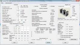 first_calc.jpg207.2 KB · Views: 69
Last edited:
240vac x 1.414 = 340vdc / 2 = 170vdc
198vac x 1.414 = 280vdc / 2 = 140vdc
Freq = 75khz
Bmax = 1200 Gauss
Ae = 3.54 cm2
I do not use a program to calculate the turns I do it manually. I especially dislike that eXcellent calculator. It is overly complicated and difficult to use. Microsims calculator is OK if you remember that the comma is really a decimal point.
170vdc x 100,000,000 / 4 x 75000hz x 1200G x 3.54Ae = 13.33 Primary turns, We could go 13 + 13 or have more safety margin with 14 + 14. After wire selection and calculated fit, we may find 1 turn makes a difference. Especially with multiple strands of wire.
N80 = 14 pri turns x 82vdc / 140vdc = 8.2 turns, once again we have a choice, 9 + 9 is only needed for the lowest line voltage input, we could just go with 8 + 8 if we wanted. Once again we will see were our wire size calculations bring us and then adjust the turns accordingly.
Now select wire for current rating and by skin effect.
I have been studding SMPS transformers for audio applications over the last couple of weeks and have found a secret to there design. In order to fit all the winding’s on the bobbin you must design for the average music level, not continuous operation at 1kw load. To do this you can go as low as 150cm/Amp (cm = Circular Mils) in the winding’s to make them fit.
undrtkr
New member
ok i'll use only MicrosiM calculator for now
thank's by correcting the min and max vdc values for my transformer, think it's look better now
i think 150cm/Amp so low then i'll use 250cm/Amp = 0.12mm2/Amp (using online calculator)
looking at AWG table, i can see the AWG26 with 0.129mm2 of area and good for 100khz
so each AWG26 wire will carry 1A right? (0.12mm2/Amp)
if i am wrong correct me please, i'm doing all these calculations from my mind
0.12mm2 / Amp
Vout = 82+82Vdc
Iout = 10A
Pout = 1640w
so 10x AWG26 for secundary should be ok
Vin = 140Vdc (worst case)
Efficiency = 70% (can be better?)
Pin = 2132W
Iin = 15.22A
so 15x AWG26 for primary should be ok
is this calculation correct?
now, how can i calculate if will it be fit in the bobbin?
i'll try to use the same original 24mm wide rolling, to preserve the safety margin
i'm learning so much wally7856, that's very good thank you again by the help
Last edited:
undrtkr
New member
no, i don't have any book about SMPS except the forum stuff
so, i got some new calculations, i made all from my mind and logic
using litz wire calculator, i got these values
1.99mm max diameter for x16 AWG26 wires
1.57mm max diameter for x10 AWG26 wires
24mm wide on bobbin for windings (to preserve safety margin)
24 / 1.99 = 12.06 turns per layer for primary (maybe i need to take 2mm of safety margin to add 1 more turn and make the primary in one layer)
24 / 1.57 = 15.28 turns per layer for secundary (if i took more 2mm of safety margin i can do all the secundary in one layer, is this ok?)
at this point i'm scared of staying totally wrong, correct me please
windows have 10mm, i've to calculate the space used by winding layers and isolation between them
to know if it will be fit
so i'm planning to roll the tranformer like this
bobbin
1 turn insulator
1st primary in one layer (1.99mm x 13 turns = 25.87mm wide / 1.99m thick)
4 turns insulator
all secondary in one layer (1.57mm x 8+8 turns = 25.12mm wide / 1.57mm thick)
4 turns of insulator
2nd primary in one layer (1.99 x 13 turns = 25.87mm wide / 1.99mm thick)
4 turns of insulator
2 turns yellow tape
so
1.99mm thick of 1st primary
1.57mm thick of all secondary
1.99mm thick of 2nd primary
5.55mm total thickness of the windings
10mm of bobbin window
was left 4.45mm for insulators
now have to calculate the space used by insulators, but based on this i think it will fit nicely
what do you think wally7856?
To make the wire calculations you need the primary and secondary current. I think you should stay with the 1kw design goal. That way you can use the 1kw SMPS schematic you found without recalculating everything.
PRIMARY CURRENT
Worst case efficency is 70% so lets say 1300 watts primary / low voltage of 140vdc = 9.28 amps.
SECONDARY CURRENT
Each 9 turn winding has to put out 500 watts. So 500W / 80vdc = 6.25A
To check our calculation look at total secondary voltage of 160vdc x 6.25A = 1000W
The only gray area here is you could make the argument that this is peak power and for RMS you have to multiply our power by .707 and get 707 watts rms. It seems to me that everyone here is just using peak power for their calculations so i usally do also. Let me know what you think and anyone else reading this please leave your comments.
Read carefully lots of mistakes, i marked them but left them in for people to learn.
For wire sizes lets work in inches and AWG because i do not have the metric formulas. When we are done then it is easy to convert to metric.
After you have the wire currents you need to know what the skin depth is for 75khz.
Skin depth in mils = 2837 / square root of f in hz = 2837 / sqr root of 75,000 = 10.359 mils = .01359" This is the skin depth for 75,000 hz, best case you use this for the wire diameter for the primary. .01359" is close to 27awg = 201cm ( cm = circular mils).
For the secondary because it is between 2 primary’s you can go 2 x skin depth. So 2 x .01359" = .02072" = 24awg = 404cm.
Primary current 9.28A x 150cm/a = 1,392cm needed. We want to use 27awg = 201cm.
1,392cm / 201cm = 6.9 strands of wire.
7 strands x .01359" x 14 pri turns = 1.33"
We have 24mm of winding width = .944"
It don't fit!
We need at least 150cm/A so we have to sacrifice skin depth to make our winding’s fit.
I will just pick a bigger wire size a few gauges up and try again.
25awg = 320cm = .0179"
1,392cm needed / 320cm = 4.35 strands. Lets call it 4 strands and see were we are.
4 strands x .0179" x 14 pri turns = 1.0024"
1.0024" - .944" of winding width = .0584" = 1.48mm to wide. Lets see what the next size wire brings us.
24awg = 404cm = .0201"
1,392cm needed / 404cm = 3.45 strands. If we go to 4 strands we will be worse than 25awg for width. But 3 strands is a little short on current. Lets try next gauge.
23awg = 509cm = .0226"
1,392cm needed / 509cm = 2.7 strands. Try 3 strands.
3 strands x .0226" x 14 pri turns = .9492" BINGO!
.9492" - .944" = .0052" = .131mm to wide / 2 for each side. This is close enough.
OOPS, i made a mistake. I used the diameter for bare wire. Magnet wire usually adds .002" to the diameter. This will add up fast. OK i looked up the diameter of 23awg heavy build magnet wire = 0.0249“
3 strands x .0249" x 14 pri turns = 1.0458" To big again.
22awg = 642cm = 0.0276" heavy magnet wire.
1,392cm needed / 642cm = 2.16 strands.
2 strands x .0276" x 14 pri turns = .7728" And guess what. MORE MISTAKES. I am leaving my mistakes in here so all can learn from them.
I am using the wrong number of primary winding’s. In a few posts above i calculated 13.33 primary turns and decided to try 14 turns. That is the total number of primary turns so we need 7 + 7 turns wired in series. GRRRR.
OK lets start over. Best case wire is 27awg.
Primary current 9.28A x 150cm/a = 1,392cm needed. We want to use 27awg = 201cm.
1,392cm / 201cm = 6.9 strands of wire.
7 strands x 0.0161" heavy magnet wire x 7 pri turns = .7889"
We have 24mm of winding width = .944" - .7889 = .155" short
It is best to fill up all layers all the way across to give you the best coupling so we will try keeping the same number of strands but using the next size wire.
26awg = 254cm = 0.0178" heavy magnet wire.
7 strands x 0.0178" heavy magnet wire x 7 pri turns = .8722"
We have 24mm of winding width = .944" - .8722" = .0718" to short = 1.824mm, not to bad but lets try next wire.
figure out were our cm/A is.
7 strands x 254cm = 1,778cm
1,778cm / 9.28A primary = 191cm, nice, better than our 150cm/A minimum.
25awg = 320cm = 0.0199" heavy magnet wire
7 strands x 0.0199" heavy magnet wire x 7 pri turns = .9751"
.9751" - .944 winding width = .0311" = .79mm to long
figure out were our cm/A is.
7 strands x 320cm = 2,240cm
2,240cm / 9.28A primary = 241cm, nice, better than our 150cm/A minimum.
I think the 26awg is the best choice in this example for the primary. Now work it out with the metric wire you can buy. And see if you can get better.
For the secondary you will have 2 winding’s of 8+8 or 9+9 depending on how it works out. Each secondary layer should use up the full winding width like the primary did.