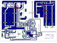
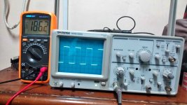
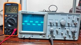
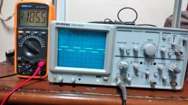
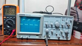
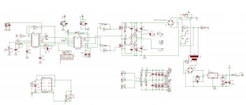
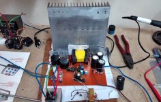
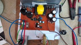
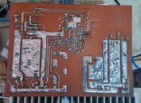
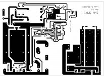
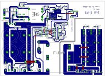
1kW smps project (based on MicrosiM design)

guys I face a strange problem
when I turn on the smps I only get 80 volts in the output with just 1.5A(with one Heater Element connected to output) but I normally get about 500W with that element (the voltage should be around 170 V normally)
The voltage drop is so huge
but when I disconnect the load the voltage come to normal

and here's the strange part:
When I connect my oscilloscope to the primary of transformer the voltage became normal and I get 500W with that element

What do you think is the problem here?
 

Jagd.Panther

New member
Any idea what could be the problem?

Can you probe with an oscilloscope secondary wiinding voltage, PWM outputs when you have this issue?

Also try to use a variac and slowly increase the voltage and observe output voltage/waveform.

Possible reaons are: undamped oscillation due to parasitics Lk/Ls and stray capacitance, oscillation of PWM chip due to high di/dt or dv/dt on nearby lanes.
 
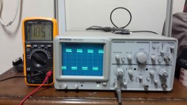
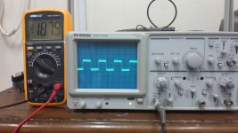
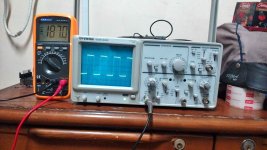
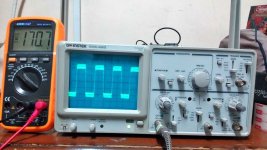
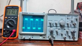
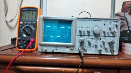
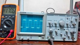
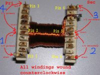
points that oscilloscope's probe and ground connected to on each picture is shown in this picture
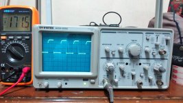
34.jpg

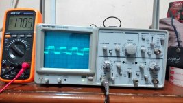
1- probe to the point 1 and ground to 3
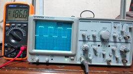
02.jpg

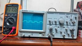
2- probe to the point 3 and ground to 1
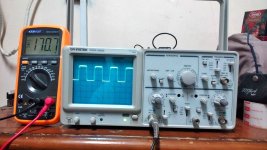
35.jpg

3- probe to the point 1 and ground to 2
36.jpg

4- probe to the point 2 and ground to 1
37.jpg

5- probe to the point 2 and ground to 3
38.jpg

6- probe to the point 3 and ground to 2
39.jpg


above pictures are taken from SMPS with NO Load connected to output
 
1- probe connected to pin 1 of IR2110 and ground of oscilloscope to ground of regulator 7815 (with no load connected)
40.jpg

2- above configuration with one heater element connected:
41.jpg

3- probe connected to pin 7 of IR2110 and ground of oscilloscope to ground of regulator 7815 (with no load connected)
42.jpg

4- above configuration with one heater element connected:
43.jpg
 
points that oscilloscope's probe and ground connected to on each picture is shown in this picture
34.jpg

1- probe to the point 1 and ground to 3
1.jpg

2- probe to the point 3 and ground to 1
2.jpg

3- probe to the point 1 and ground to 2
3.jpg

4- probe to the point 2 and ground to 1
4.jpg

5- probe to the point 2 and ground to 3
5.jpg

6- probe to the point 3 and ground to 2
6.jpg

above pictures are taken from SMPS with one Element connected to output
 

blasphemy000

New member
Are you running this supply from the mains while you're probing it or do you have your SMPS connected through an isolation transformer? Every time you connect the ground clip of your scope probe to any point in your circuit, that point is referenced to Earth, through the scope.

Other than that, it appears that something is clamping the voltage between points 2 & 3 on the secondary of the transformer. Blown diode or a short in the secondary maybe?
 
I try something and it did work

when I connect the oscilloscope probe to ether pin 1 or pin 7 of IR2110 and the ground of oscilloscope to the ground of 7815 regulator without the cable connected to oscilloscope I also get the full power and everything is ok
 
Are you running this supply from the mains while you're probing it or do you have your SMPS connected through an isolation transformer? Every time you connect the ground clip of your scope probe to any point in your circuit, that point is referenced to Earth, through the scope.

Other than that, it appears that something is clamping the voltage between points 2 & 3 on the secondary of the transformer. Blown diode or a short in the secondary maybe?


No I just connected the smps directly to the main without any isolation transformer
 
why the two output rails voltages on the oscilloscope are not the same???(on the multi-meter each rail has the same voltage ether with load or without it)
Do you think that the problem is from output diodes?
transformer winging start and end points can cause this????
 
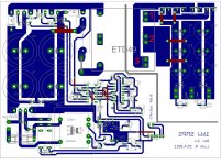
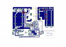
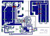
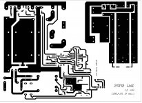
Here's the pictures from PCB: (I used V2.1 PCB of ludo3232 design)

10.jpg 11.jpg 14.jpg


7.jpg

8.jpg

9.jpg

I also rotate the original PCB for better comparing:
12.jpg 13.jpg

Thank you for your helps
 

Jagd.Panther

New member
Please try to do the following:
- Connect Pin3 of SG3525 to ground, you can use few kiloohm resistor.
- Connect the heatsink to the LV-side ground.
- Connect HV-side ground to the LV-side using 2200pf/3300pf/4700pf X rated ceramic capacitor (or just use any other ceramic capacitor for 2-3kV+).


- I dont see any snubbers across pirimary or FET's D/S. Do you have them? If not, please install them, like 100-200 ohm / 220-470pf@2kV across D & S of each FET.
- Install snubbers across each half of secondary winding,
 
Top