everything are the same as ludo schematic except for these:
1- I replace D9 that was MUR120 to MUR460
2- for input rectifier I use KBPC3510W
3- Changed the FETs to IGBTs
4- Replace the output bridge diodes from MUR810 to MUR1520
5- Instead of using 2x1000uf cap for each rail of input I use 3x680uf
6- I just install 2x1000uf for each rail of output instead of 3x1000uf
7- Connection between Heatsink and Low voltage ground
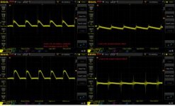
8- Connecting Oscilloscope probe to gate of Q1 and low voltage ground
View attachment 5470
Those are the whole changes from my current smps than Ludo's
View attachment 5471 View attachment 5472 View attachment 5473 View attachment 5474


") Without stabilization.
Without stabilization.