You are using an out of date browser. It may not display this or other websites correctly.
You should upgrade or use an alternative browser.
You should upgrade or use an alternative browser.
1kW smps project (based on MicrosiM design)
- Thread starter ludo3232
- Start date

res
I am doing LLC smps now and have exacly the same question
The circuit no2. the series capacitor is in splitted configuration so the primary will sie dynamic capactance of 2uF. The currents are splitted too.
At the ST document about LLC at page 64 this splitted config is explained a bit better. The circuit no 2 should be a better one, caps can be lower - 470nF in this case, there is less current going threw them, the startup should be better.
Jagd.Panther
New member
First one gives you an easy way to use voltage doubler and run from 110/120V mains. Second one doesn't.hi,
can someone explain me what is the difference of this circuit, advantage or disadvantage?
View attachment 5587
thank you
There is also minor difference on peak currents through caps but I think it's kind of negligible.
res_smps
Member
thank you borysgo2 and panther,
is there any probability of voltage imbalance with circuit number 2?
which document did you refer to?At the ST document about LLC at page 64 this splitted config is explained a bit better.
i agree with you, mass product prefer using first circuit.First one gives you an easy way to use voltage doubler and run from 110/120V mains. Second one doesn't.
There is also minor difference on peak currents through caps but I think it's kind of negligible.
is there any probability of voltage imbalance with circuit number 2?
Jagd.Panther
New member
Nope, these circuits are pretty much equivalent.is there any probability of voltage imbalance with circuit number 2?
You can follow star-delta transform and calculate exact equivalent. For example for one 470uf bulk cap and a capacitor divider made of two 1uf caps the equivalent would be 941uf bulk caps in series + 2uf cap.
Jagd.Panther
New member
High voltage caps are usually very expensive; also PCB area is often not an issue in DIY. In other words I'd compare prices for the caps and opt for the cheaper solution.
res_smps
Member
Nope, these circuits are pretty much equivalent.
You can follow star-delta transform and calculate exact equivalent. For example for one 470uf bulk cap and a capacitor divider made of two 1uf caps the equivalent would be 941uf bulk caps in series + 2uf cap.
thank you panther, that is very clear for me

badboy_6120
Member
Hello "Jagd.Panther"
the problem with protection (at startup) is from output caps
Should I use the same method as Input caps for it??? (use Resistors bypassed by timed relay) or is there better solution???
the problem with protection (at startup) is from output caps
Should I use the same method as Input caps for it??? (use Resistors bypassed by timed relay) or is there better solution???
Jagd.Panther
New member
Hello "Jagd.Panther"
the problem with protection (at startup) is from output caps
Should I use the same method as Input caps for it??? (use Resistors bypassed by timed relay) or is there better solution???
Please post actual schematic you use (with all of the changes you've ever made)
Jagd.Panther
New member
Please post actual schematic you use (with all of the changes you've ever made)
P.S. Also be sure to update component values if you changed them.
badboy_6120
Member
Please post actual schematic you use (with all of the changes you've ever made)


Jagd.Panther
New member
So you have 1500uF bulk caps on the pirmary side and 3000 uF per rail on the secondary side, right?
What relay do you use? Voltage/winding resistance?
Did you try to change C16 to 46uF? Change R1 to 15 ohm (connect 33ohm resistor in parallel)?
badboy_6120
Member
In the current board I have 3x680uf on each rail of primary and 3x1000uf on each rail of secondary, but in my pcb I'm going to put 4x680uf and 4 or 5x1000ufSo you have 1500uF bulk caps on the pirmary side and 3000 uF per rail on the secondary side, right?
a dual contacts 12V relay with 278 ohms winding resistanceWhat relay do you use? Voltage/winding resistance?
I put a 47 ohms resistance in series with relay winding to put about 12 volts on it
I did that with no luck (same result)Did you try to change C16 to 46uF?
I use 4 x 3.9 ohms /10W resistors in seriesChange R1 to 15 ohm (connect 33ohm resistor in parallel)?
now with no load the smps starts normally but not with load
Jagd.Panther
New member
So with 47uF softstart cap and 4x3.9 ohm softsart resistor the SMPS starts without load but fails to do that with load?I use 4 x 3.9 ohms /10W resistors in series
now with no load the smps starts normally but not with load
Jagd.Panther
New member
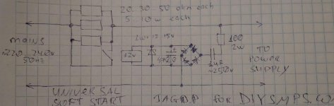
Soft start circuit based on 555 timer like the one you use has no feedback whatsoever. I suggest using circuit like the one in the attachment. It works with SMPS and with conventional (linear) power supplies.
Attachments
-
 soft-start.jpg68 KB · Views: 171
badboy_6120
Member
So with 47uF softstart cap and 4x3.9 ohm softsart resistor the SMPS starts without load but fails to do that with load?
changing SG3525 softstart cap to 47uf doesn't change anything (Same result as 22uf)
But by lowering down the inrush limiter resistor to 15 ohms, smps start normally without protection triggering
but with load (like less than 1KW) I have to switch on and off the smps a few times (mostly two times works but never at first time) to start it
Last edited:
badboy_6120
Member
Soft start circuit based on 555 timer like the one you use has no feedback whatsoever. I suggest using circuit like the one in the attachment. It works with SMPS and with conventional (linear) power supplies.
Is the electrolytic cap 4700uf ????
Jagd.Panther
New member
Is the electrolytic cap 4700uf ????
it's 470uf
badboy_6120
Member
it's 470uf
So I used the inrush limiter that you advised and now with about 1100W load connected, smps starts normally and I think It's good since My amplifiers protection takes about 2 or 3 seconds to connect the Subwoofers to amplifiers ouput
How do I know that this is a good point for protection to kick in???
I think now the protection set to about 15A at primary of the transformer since I can connect less than 2KW load without triggering the protection but not more than that
Is this good????
badboy_6120
Member
I connected the extra Caps that I want to use in my pcb design and the above result are with those
input >>> 4x680uf in each rail
output >>> 5x1000uf in each rail
input >>> 4x680uf in each rail
output >>> 5x1000uf in each rail