You are using an out of date browser. It may not display this or other websites correctly.
You should upgrade or use an alternative browser.
You should upgrade or use an alternative browser.
1kW smps project (based on MicrosiM design)
- Thread starter ludo3232
- Start date
Hi Microsim,
We thank you for all the efforts you put in this place. I enjoy reading all about everybody's effort in keeping this great site.
If I am not mistaken SG2525 is the same as SG3525 but with better performance especially in withstanding temperature.
Cheers.
To tell you truth, I had no time to check it out! So I cannot comment!
Thanks for your feedback about diysmps
Hi Guys,
So far so good, I am still messing around with theory of SMPS, it is amazing how they work; I will be using SG3525, it is a great IC, the shut down input will be used to detect primary over current to protect MOSFET from blowing up (using a sense resistor in series with the H-Bridge), and the error amplifier to regulate the output voltage, these 2 mechanisms will provide protection against short circuits and over voltage (in addition to fuses and other stuff).
the SG3525 will drive 2 IR2110 that will drive 4 IRFP460 (or maybe other Ref, I have a lot of MOSFET and IGBT in my box) , the feedback will be around the famous TL431 precision reference and an optocoupler to provide galvanic isolation between in/output.
I highly recommend you guys to go through "Power Supply Cookbook Second Edition by Marty Brown" very helpful book with a lot of theory and practical examples.
I will be posting schematics and some results in few days, the way I am going through this project is a "Block by Block", the first thing I did is get familiar with SG3525, I made it work as I expected, I used a potentiometer to change the duty cycle, also playing with IR2110 with 2 IRF1010 MOSFET in half bridge config with a resistor as a load, things were fin.
Next will be combining both (SG3525 and IR2110) with some resistive load; just to let you know, I am using 12V battery to supply my setup, I do not want to mess with 310VDC at this stage.
Right after will be the transformer design, and the ultimate step of assembling every thing together, put eyes protection and give it some heavy juice (in series with a bulb of course)!!!
any advice is welcome.
and think a lot about safety.
Regards,
RABSMPS.
Hi Microsim!
My design is based on Ludo's v2.1 schematic. I modified the Sg2525's circuit as you posted before, but with 15V supply. Here are some pictures about the SMPS:
This is the signal on my Sg2525 outputs:

This is the signal on the IRFP460 gates:

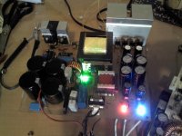
And these are the pictures of the SMPS:


I had to switch the two signal lines that goes from IR2110 to IRFP460, I made that mistake when I made the PCB plan. The protection circuit is also on this board, but that didn't work, so I disconnected it. There are also some regulators for +-12V, 12V and 5V, it's not finished yet, my main scope is to make the +-90V work. There are some glitches after the signal goes from high to low and before the signal goes low to high. I don't know why is that...
Thank you for your help!
My design is based on Ludo's v2.1 schematic. I modified the Sg2525's circuit as you posted before, but with 15V supply. Here are some pictures about the SMPS:
This is the signal on my Sg2525 outputs:
This is the signal on the IRFP460 gates:
And these are the pictures of the SMPS:
I had to switch the two signal lines that goes from IR2110 to IRFP460, I made that mistake when I made the PCB plan. The protection circuit is also on this board, but that didn't work, so I disconnected it. There are also some regulators for +-12V, 12V and 5V, it's not finished yet, my main scope is to make the +-90V work. There are some glitches after the signal goes from high to low and before the signal goes low to high. I don't know why is that...
Thank you for your help!
That wave is 100% INCORRECT, and it will blow up your mosfets without any warning
Your PCB looks bad to me, I am sorry to tell you this.
I dont know where did you get this PCB design from? Ludos PCB looks different.
I really dont know how I can help you with that setup.
1- Distance from IR2110 to Mosfets are too long
2- Mosfets heat sinks installed in dangerous way
3- Bridge you are using is too small for this SMPS
4- PCB track (high voltage track) is very close to screw, this may end your life in any minute
My personal advice to you is to check other guys who made a successfull SMPS, and see the PCB how they made it, or ask for one ready
Or, you can make a new design of PCB, while taking advice from us, and post every step here
SMPS is not a JOKE to work with, and you recognize that I think
Please let me know what do you think
Regards
 I just hoped that it can be fixed, because I will have no time to build in the next 2 months, I have some exams at the university. But after that I'll try again.
transformer
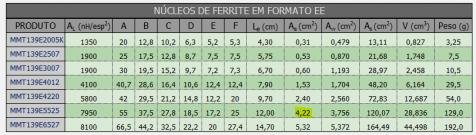
good night MicroSim am in the process end of my board rev 3.1, I'm just in doubt with the transformer input 120 vac table with voltage doubler to 340. output
symmetrical with 80 Vdc, 1kw 75KHz, the program was the result, eight primary back 0.64 mm x 10, secondary 10 +10 0.64 x 6 laps laps, this calculation, that's right.
Attachments
-
 download.jpg20.6 KB · Views: 227


vorezky04
New member
Please come and coment
http://www.diysmps.com/forums/showt...smps-1kw-design-by-microsim..&p=5579#post5579
http://www.diysmps.com/forums/showt...smps-1kw-design-by-microsim..&p=5579#post5579
Hi Microsim!
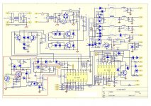
I didn't get any already made PCB, so I redesigned mine based on the rev 3.1 PCB uploaded here. I wired the SG2525 following your uploaded pdf:
PWM-Drive2.pdf
There's 18V in that pdf. Is 15V enough? Because 18V would be too high for NE555. I moved the screws to less dangerous place. You told me that the rectifier bridge is too small. It's 600V 8A. Should I change it to bigger one?
Here's the PCB:
high resolution:
PCB
Please tell me what you think and what should I change.
Thank you!
