You are using an out of date browser. It may not display this or other websites correctly.
You should upgrade or use an alternative browser.
You should upgrade or use an alternative browser.
20000 watts per channel
- Thread starter vedmitra
- Start date
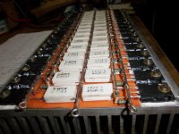
Ran out of money, but partly.View attachment 3471View attachment 3472Has anyone built this amplifier?
Sad about being from Denmark is, that this output stage costs the same as a spaceshuttle
") . I simply cannot understand how You guys can afford to do all these good works .
. I simply cannot understand how You guys can afford to do all these good works .The driver part works perfectly and with only 4 sets of output trans's it work, but not for 20kW though
.vedmitra
Member
Well Mr. Malmir, I think you should have read #7 of this thread, I am again repeating it.
I have seen that design earlier, as I have told theorticaly Amps can be made of thousands of wattage and can be made practicaly also.but as I earlier said, to run this short amps one will need gigantic power supplies,the circuit i put is basicaly 2500 watts into 4 ohm,load can be taken down to 0.25 ohms and simulations show same characterstics , but to tolerate that short of current output minimum 100 pairs of output transistors will be needed, material I have is only 50 pairs of transistors and traffo of 14400 watts primary,with this i will be able to achieve around 8000 -to- 9000 watts both channel.that is more than sufficient for me.
and the design I posted on #42 is only 1.9 K.W. with 10 pairs of 5200 and 1943 can be achieved, not costly I assume.
I had read that and i agree, hmm partly. If You do an amp like that You sure knows about switching supplyes to, and that would not be gigantic. I have seen several supplies at only 15 * 5 * 5 cm3, at 4kW and more. if we roughtly multiplys it would be 15 * 20 * 5 and that is not gigantic, at least not in my view. I would be satiesfyed with less, I just liked this mammut amp . Why the need of 100 pairs ? Sure i am missing some parameters somewhere :-(.
The one in #42 ? my guess is 200USD for output pairs alone, the PCB some 250 - 500 USD depending on how many, the rest loosly components near 50USD. That is 750USD for one board/channel only and no power supply. To costly for my salery.
. Why the need of 100 pairs ? Sure i am missing some parameters somewhere :-(.The one in #42 ? my guess is 200USD for output pairs alone, the PCB some 250 - 500 USD depending on how many, the rest loosly components near 50USD. That is 750USD for one board/channel only and no power supply. To costly for my salery
.vedmitra
Member
Thanks Mr. Malmir for reply, 5200 and 1943 here in India cost only Indian Rs. 80-00 a pair, and mj15024 , 15025 Indian Rs. 300-00 a pair.As I earlier said I have 50 pairs of original Motorola !5024 , 15025 with me.About Transformer for 1 kw power out in class ab minimum 1.75 Kw transformer is needed.
Attachments
-
 Real gold.JPG235.8 KB · Views: 103
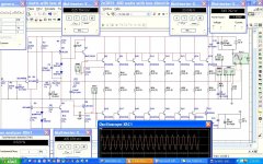
scheme
night sir,... u've finish with board,... what the yellow had true for conected or not conect?... or pls send me/reuploud with succes scheme,.. i'll build this one for my hobby,...
thanks n regards
Well there were some faults in the design I sent now , corrected design,and it gives amazing results,around 1.9 kw at only 0.002% distortion.on 2ohm 0.001% distortion,on 4 ohm0.0005% only.So I have named it "ULTRA CLEAN".
night sir,... u've finish with board,... what the yellow had true for conected or not conect?... or pls send me/reuploud with succes scheme,.. i'll build this one for my hobby,...
thanks n regards
Last edited:
vedmitra
Member
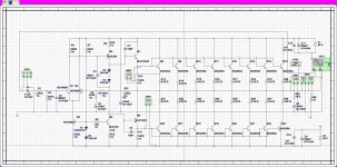
nice copied photo Sameerx-1 and Andrew Lebon,just one question what is supply for it??? In my opinion it should be around 9 Kw. minimum for both chanelles,and how many voltage you are getting on output, assuming 70 volt, current should be around 42 amps in output, zobel inductance shown in your copied photo can it pass 42 amps???.be sensible
vedmitra
Member
Hello Martha 78 yellow line also to be connected , driver section use Uncle charlie's dx super a board as it is modification of that only, emmitter and base resistances of output transistors can be connected on main heat sink like I have done
Attachments
-
 Copy of 100_1711.JPG218.5 KB · Views: 143
6000w
Nice sir,.... mmm great PA... I hope to try it, only curiosity and a wish .. but i've not scheme
Hello Martha 78 yellow line also to be connected , driver section use Uncle charlie's dx super a board as it is modification of that only, emmitter and base resistances of output transistors can be connected on main heat sink like I have done
Thank u sir,... very helpfull
the first from mid PA and go to Higher PA... nice job for u sir...
vedmitra
Member
500 watts with 2n3055
friends here I present a circuit with old trustworthy metal 2n3055, supply rail 55-0-55 v. d.c. , distortion only 0.62% , output voltage at 2 ohm's load more than 33 volt around 550 watts,at 1 volt input signal.one can use 5200 also .
friends here I present a circuit with old trustworthy metal 2n3055, supply rail 55-0-55 v. d.c. , distortion only 0.62% , output voltage at 2 ohm's load more than 33 volt around 550 watts,at 1 volt input signal.one can use 5200 also .
Attachments
-
 2n3055 with 55-0-55 volt.JPG207.5 KB · Views: 83
 -
 Copy of 3055 modified.JPG274.3 KB · Views: 124
friends here I present a circuit with old trustworthy metal 2n3055, supply rail 55-0-55 v. d.c. , distortion only 0.62% , output voltage at 2 ohm's load more than 33 volt around 550 watts,at 1 volt input signal.one can use 5200 also .
NONSENSE,
how can you power a 2N3055 which is a 60V device from 110V rail voltage? Also the circuit in simulation lacks many things + this is not real world behaviour.
Last edited:
ravpreet420
Member
i m totally agry with youNONSENSE,
how can you power a 2N3055 which is a 60V device from 110V rail voltage? Also the circuit in simulation lacks many things + this is not real world behaviour.
vedmitra
Member
Mr. Kanwar , being a senior member I always respected you, but instead of advising the Language you used,does it suit you? Even though keeping suggestion by you in mind I have changed the design to 45-0-45 volt d.c. rail ,and for your kind information I am using 2N3055H RCA transistors,which is 100 volt device and in practical 20 years ago I have used it up to 110 volts.I hope in future suggestive Language from respected Members. Mr. Microsim please see to this kind of language.
Attachments
-
 2n3055 45-0-45volt.jpg455.2 KB · Views: 70
 -
 2N 3055 with 45-0-45a.JPG211.6 KB · Views: 42