blackpower
New member
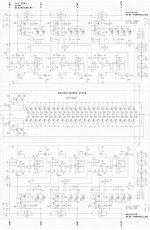
this is not a joke but a real 4000watt rms audio power amplifier
Attachments
-
 1-ed34a96df3.jpg727.8 KB · Views: 1,037
") . And i am not good at writing info on burned CD's, thus it takes time to find.. Actually we did this at engineer school and it do work as a single unit (5kW), but cannot remember if we changed some values here and there .
. And i am not good at writing info on burned CD's, thus it takes time to find.. Actually we did this at engineer school and it do work as a single unit (5kW), but cannot remember if we changed some values here and there .
 . If Your simulation models are rather good, try simulate what the impact will be when changing. My first guesstimate will be a hand full of resistors should be changed too, but not more than that. ...