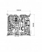
600W SMPS with IR2153 and 2xATX transformer

maxente

New member
Here is my latest power supply with IR2153 and 2 transformars salvage from cheap ATX power supply
Few years ago i saw an experiment with IR2153 and 2 x transformer ATX on 320volt.com and i decidet to try it
Of course this power supply has a short circuit and/or overload protection with a current transformer and a simulated thyristor with 2xBCxxx transistors
Also this power supply has a soft start with an 30-40R NTC in series with power transformer shorted by a relay after aprox. 1 second

In this picture you can see first DMM measuring voltage on load and second DMM measuring current through load


In this two pictures you can see the power supply with no load and next with load over 600W


If somebody wants to try this power supply, here you have an archive file with schematic and pcb
 

Attachments

  • SMPS 600W.rar
    92.2 KB · Views: 1,831
Last edited:

MicrosiM

Administrator
Staff member
Looks very nice, and well done.

It would be great if you can add a video showing the short circuit action, also the SMPS under load.

This looks great project for many folks who is looking for easy SMPS.

Thanks for sharing.
 

MicrosiM

Administrator
Staff member
Thanks for sharing. Could you please tell me why you limited the inrush to the transformer.


I am sure that "Maxente" had problems without using that inrush limiter.

But to be honest, the only way to make a successful SMPS using IR2153D is to use a Proper inrush circuit for the transformer primary as shown in schematic.

If you remove that section, be sure that your Mosfets will die the minute you overload your SMPS, or if the SMPS faces full load, or short circuit.

Also pay attention to his running frequency, 30Khz, witch is LOW and this makes the SMPS more stable!

I also read somewhere long time ago, that IR253D has some problems with the startup mechanism and cannot remember exactly where.

I quit using that chip due the start up problems, and blowing mosfets due that reason, very short start up time is a major problem in that chip.

And finally I found a better chip than IR2153D that fits perfectly my 600W RMS, 1000W Peak SMPS sized 12CM x 10CM

Hope that helps.
 

demykiko

Member
Very nice work Maxente. You can inspire us doing DIYSMPS continuously despite some failures. Thanks for your sharing.
 

maxente

New member
Thanks everyone for your appreciation !
@wally7856 during testing i realized that is nearly impossible to power on this power supply. The protection is triggered instantly. If I remove the protection you can power on witout blowing the mosfets, but in case of an overload or short circuit the mosfets will not survive, i know because i tested. This the limitation for this IR2153
Ohh... I forgot to mentioned, if somebody try this power supply I recommend to use one heatsink on mosfets and another heatsink on rectifier diodes in secondary power transformer for electro-security reasons
I made 4 pcb and second power supply is up and running
 

maxente

New member
Yes, those two transforme are unmodified
That's the point, to make a power supply as simple as possible and with salvage parts
From some old or damage atx power supply i use EMI transformer, those two big caps if they ar good (measure with ESR) and power transformer
Power transformer must be from power supply with half bridge topology
It may work with transformers from power supply that use forward topology, but you need to test
It will not work with transformer from flyback power supply, those transformer have air gap
 

Jagd.Panther

New member
Thanks everyone for your appreciation !
@wally7856 during testing i realized that is nearly impossible to power on this power supply. The protection is triggered instantly. If I remove the protection you can power on witout blowing the mosfets, but in case of an overload or short circuit the mosfets will not survive, i know because i tested. This the limitation for this IR2153
Have you thought about adding soft start circuit? It's possible to either run IR2153 on higher frequency (it has fixed dead-time, so increasing frequency reduces duty cycle) or run it with asymmetrical on time by providing feedback from one of the output to Rt/Ct.

BTW it's possible to get like +/- 50v from just one transformer, you have to run on 2+ time higher frequency and supply it with twice input voltage (either use a fullbridge @ 300v or half-bridge @ 600v from voltage doubler).

I reworked an ATX power supply like that: removed SG6105D, installed cheap 900v FET's and shaped few tracks by cutting extra to get enough spacin on HV sideg, added GDT + gate driver with negative bias (driven by SG3525 @ 95 KHz), reworked rectifier so to get 600v DC, changed snubbers and aux power supply connection. Works OK, Trafo get's barely warm on idle so ferrite losses are OK and the only concern is increased losses by due to skin effect. Going to add an OC protection.
 

maxente

New member
With NTC connected in series with primary of transformer is ok, no need for another soft start and i can power on with 300w load
The power supply is working at about 30khz
 

maxente

New member
From what i see you don't use output inductor
This version of yours have a soft start ?
Please post your schematic for this version
 

jayadev

New member
Can you share the Output transformer and current transformer winding details, As I want to wind it myself,turn by turn.
 

jayadev

New member
You can calculate your trafo whit this xcel file https://drive.google.com/file/d/0BxkSTRzdWMTjNV9FTXZpdzNOTk0/view?usp=sharing
To open the file you do not need password. If it ask you for password you can type anything
The curent trafo i windi it a small ferite ring with 40 turns

Thank you.

I have difficulty in procuring components at my locality so I am ordering them online from different website. So it will be a gradual process building and learning the art of making smps. I expect your help.

This would be my first smps.

Regards.
 

marian_milea

New member
Hy,i am new in this forum and i whant to learn more about SMPS .I decide to build the smps from Maxente and need some help from you guys.
I found a HF transformer from a atx power supply and i realise he has 3 tensions in the secondary, for 5v, 12v, and 3v.I am right?
From i anderstand if i change the number of turns in the secondary i will obtain the voltage i whant ( 2x45V in my case).I whant to power ap a 2 chanel 100W amplifier.
 

Fino

New member
Hi guys,
I'm really interested in building this supply, but I have two questions, the trimmer is for output voltage regulation? Aaand about that current Transformer, 40 turns on secondary and only one on primary or what?
Thanks
 

mone

New member
No, trimmer is for sensitivity overload protection.

Yes, sense 1 turn for primary, 40turns for secondary for overload protection.
 

Voitano

New member
Sorry, I dont understand, why are you using this chip(IR2153), that was not intended for this kind of SMPS. Tl494 is in almost every old atx PSU. You can make voltage and current regulation easily. And as gate driver you can use IR2106 e.g.
 
Last edited:
Top