You are using an out of date browser. It may not display this or other websites correctly.
You should upgrade or use an alternative browser.
You should upgrade or use an alternative browser.
Another IR2153 smps
- Thread starter borysgo2
- Start date
A bit off topic but it might be helpfull.
I have done some small tests on a new board, for now without tweaking the parts values.
Bellow few scope readings how does the current sense work in more traditional aplication of half-bridge smps.
Yellow trace --> primary voltage
Blue trace --> current sensor voltage (AC coupled)


With a few component values changed the circuit can be more sensitive to the load.
I am just wondering if it is 100% correct and safe in use --> the capactive current sensing.
And the rubbish made off board itself:

And both small and bigger one:

I have done some small tests on a new board, for now without tweaking the parts values.
Bellow few scope readings how does the current sense work in more traditional aplication of half-bridge smps.
Yellow trace --> primary voltage
Blue trace --> current sensor voltage (AC coupled)
With a few component values changed the circuit can be more sensitive to the load.
I am just wondering if it is 100% correct and safe in use --> the capactive current sensing.
And the rubbish made off board itself:
And both small and bigger one:


The last picture is the older project (developed for last two or three yeares). It is module amplifier (i-AMP), separate output stage and a few input stages (similar like slewmaster project at diyaudio.com).
I have made 4 or more output stages, with bipolar transitors (2,3,4 pairs) and one double bootstrapped mosfet output stage for subwoofer (whrere drivers voltage is bootstrapped from negative and positive rail, so the output is swinging nearly rail to rail, the Vgs voltage is not wasted anymore).
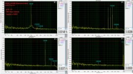
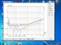
This is the example of THD and IMD plots for IPS board with ECC88 tube + BJT output stage (you will never find a combo like this ).
).

OPS wit 4 pairs

OPS with 3 pairs

Cliffjumper IPS board at work

But the main question is why ?
That is why

Before I had to build a prototype every time I have made something new, now I will have to change only 7cm x 7cm driver board.
The same I have made with SMPS, that is why I have started i-SMPS project, You are building main board which can take a universal driver boards made whatever you want. No need to solder whole SMPS again. Work is 10000% faster going this way.
So now I have i-AMP and i-SMPS projects, both are interesting but second one is more dangerous.
Regards
I have made 4 or more output stages, with bipolar transitors (2,3,4 pairs) and one double bootstrapped mosfet output stage for subwoofer (whrere drivers voltage is bootstrapped from negative and positive rail, so the output is swinging nearly rail to rail, the Vgs voltage is not wasted anymore).
This is the example of THD and IMD plots for IPS board with ECC88 tube + BJT output stage (you will never find a combo like this
).OPS wit 4 pairs
OPS with 3 pairs
Cliffjumper IPS board at work
But the main question is why ?
That is why
Before I had to build a prototype every time I have made something new, now I will have to change only 7cm x 7cm driver board.
The same I have made with SMPS, that is why I have started i-SMPS project, You are building main board which can take a universal driver boards made whatever you want. No need to solder whole SMPS again. Work is 10000% faster going this way.
So now I have i-AMP and i-SMPS projects, both are interesting but second one is more dangerous
.Regards
Attachments
-
 THD plots.jpg20.2 KB · Views: 35
 -
 thd15v.jpg19.5 KB · Views: 22
 -
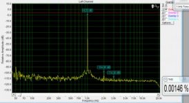 1k.jpg20.8 KB · Views: 22
Last edited:
My first SMPS the voltage droped when connect to load.
Before connected to load the voltage is 16.6 V but after connect to load become the voltage 12.2 V and 4.8 A.
My target is 15V 20A. I user ferrite core EER40. Primary np=2x12n 0.5mm 4 strands and secondary ns=3n 0.5mm 8 strands.
Please advice.
Thankyou.
Before connected to load the voltage is 16.6 V but after connect to load become the voltage 12.2 V and 4.8 A.
My target is 15V 20A. I user ferrite core EER40. Primary np=2x12n 0.5mm 4 strands and secondary ns=3n 0.5mm 8 strands.
Please advice.
Thankyou.
I have made another driver board for i-SMPS.
This time it is based on UCC25600. Just take a look, a few components only, and you have :
-very very low standby current (startup from the resistor !!), no extra transformer required
-very powerfull driver IR2110
-soft start
-two stage over current protection
-very easy DT adjustment (no problems with max duty as with SG3525 anymore, you can adjust it to 49% if you wish to do)
-no current sense transformer required, simple reactive divider only
-standard and LLC SMPS capability at the same board (only two capacitors change with wima MKP10 series and wind the integrated trafo)

board 28mm x 38mm
I will post some further work later on.
Regards Peter
This time it is based on UCC25600. Just take a look, a few components only, and you have :
-very very low standby current (startup from the resistor !!), no extra transformer required
-very powerfull driver IR2110
-soft start
-two stage over current protection
-very easy DT adjustment (no problems with max duty as with SG3525 anymore, you can adjust it to 49% if you wish to do)
-no current sense transformer required, simple reactive divider only
-standard and LLC SMPS capability at the same board (only two capacitors change with wima MKP10 series and wind the integrated trafo)
board 28mm x 38mm
I will post some further work later on.
Regards Peter