Hello
Last year I was playing a bit with IR2153 and I have burned a good few mosfets and IC's. Have had also a problem with over current protection (used MCR100 to shunt Ct pin to ground).
This month I decided to start the project from the scratch again.
I found a few key factor to make good and stable circuit for this simple controller.
First issue, IC power supply.
Must be stable at all conditions, startup resistor is not too good solution so I have supplied the controller from the constant current source (voltage independent - extremly important during startup!!), the CCS is turning on after main caps are charged to approx 170V, the ccs is powering up the IR2153 threw stabilised supply unit (MPSA42+zener), after SMPS is ON it is supplying itself from the AUX winding and the supply unit with CCS is turned OFF.
Second issue, not stable startups.
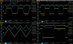
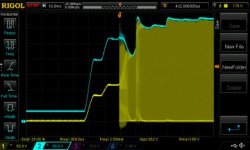
In all IR2153 projects I found the bootstrap capacitor is approx 10uF as in datasheet, I have checked the startups with 10uF, 4,7uF and many lower values, the problem is time to charge it.
At switching frequency approx 50-70kHz the 100nF is really enough to drive the IRF740 mosfet. I left on the board 470nF wchih is working very well. If you go to the IR2110 datasheet You can calculate bootstrap capacitor value yourself more accurate.
Soft-start.
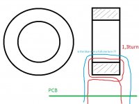
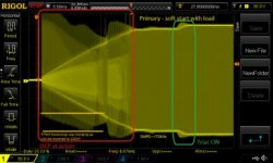
I have used NTC thermistor parallelled with triac, single turn at the main trafo does the job for turning it on. For lower power aplications it should be OK.
Yes I have burned a few mosfets but it was only my fault. I have failed with protection circuit using MCR100, so I decided to use transistor. Now SMPS does not need to be plugged out from the mains to reset. The OCP works fine, it hepls even at the startup with high load connected (or short circuit) to the secondary.
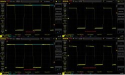
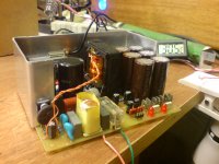
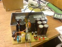
I have no idea if the project is technically OK but it works very well.


