Asking help from Microsim

demykiko

Member
Hello sir Microsim,

I observe that you are a pioneer in diy smps based on your several smps projects posted here..and I am glad to tell you that I am also your follower.
I just want to ask some questions regarding the operation of my own handmade smps whether it is ok or not and also some advices from you..Im very grateful if you will..

1. Is it normal that when I squeeze my EC-35C transformer from ATX power supply to give 650 watts of power to my flat iron load which is 45 ohms with 160 volts dc measured at its two terminals , the two power mosfets K2698 (same as IRFP460) to heat up in less than a minute? but the heating of heatsink is gradual..Im just wondering what might be the reasons becoz I can feel the two mosfets cannot handle it for a long time and might become shorted afterwards..

Regards,
Demykiko
 

MicrosiM

Administrator
Staff member
I recommend that you show a picture of your work, to take a better idea.

The Mosfet you are using, is just OK for the SMPS, I don't have much information's about the core you are using.

What is the size of your heat sink?

How many watts you are drawing from your power supply?

Regards
 

demykiko

Member
Thanks a lot sir for your response..the heat sink that i used is from old atx pc power supply..
which maybe about 8cm long and 5cm wide and the thickness is about 3mm..what do you think this size is maybe not just enough for the power
im drawing from my core EC-35C which is 650watts or maybe because the core cannot be squeezed up to that power..If im not mistaken the core which is from
atx pc power supply is rated for 350watts..but when i just draw 300 to 350watts from it my heat sink is normally hot that even our finger can endure that heat for a long time.. my very big question to you sir is this..Is it the type of core that is responsible in giving enough power without mosfets quick overheating? what i mean is if the core is for 300watts is it right to squeeze 650watts from it..or i have to use other core like ETD 49 (which is hard to find in our country)..to make my mosfet's temperature normal?..i will include picture as soon as my cp camera becomes ok..

thanks and regards,
demykiko
 

demykiko

Member
Thanks a lot sir for your response..the heat sink that i used is from old atx pc power supply..
which maybe about 8cm long and 5cm wide and the thickness is about 3mm..what do you think this size is maybe not just enough for the power
im drawing from my core EC-35C which is 650watts or maybe because the core cannot be squeezed up to that power..If im not mistaken the core which is from
atx pc power supply is rated for 350watts..but when i just draw 300 to 350watts from it my heat sink is normally hot that even our finger can endure that heat for a long time.. my very big question to you sir is this..Is it the type of core that is responsible in giving enough power without mosfets quick overheating? what i mean is if the core is for 300watts is it right to squeeze 650watts from it..or i have to use other core like ETD 49 (which is hard to find in our country)..to make my mosfet's temperature normal?..i will include picture as soon as my cp camera becomes ok..

thanks and regards,
demykiko

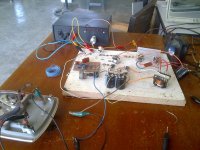
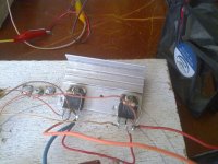
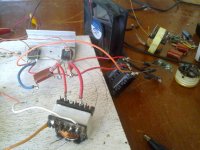
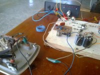
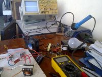
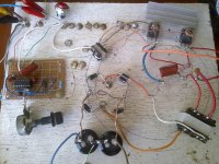
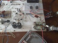
here are the pictures..

Image2214.jpgImage2216.jpgImage2217.jpgImage2218.jpgImage2219.jpgImage2220.jpg
 

blasphemy000

New member
There is a major problem with your circuit layout. With the parts just hooked together spread across the bench like that, and the long runs of wire, there is going to be a lot of stray inductance and also those long leads act like antennas and the high-current switching leads can interfere with your signal leads and cause all sorts of problems. I've made prototypes with stuff just laying on the bench, and I've always had unwanted results. Even building on a prototype punch-board would be better than just having the leads laying lose on the bench. With the wild layout you have going on there it would be hard to tell if the problem was with the circuit or with the layout itself. Maybe somebody else can chime in on this.
 

demykiko

Member
Bad method of prototyping

There is a major problem with your circuit layout. With the parts just hooked together spread across the bench like that, and the long runs of wire, there is going to be a lot of stray inductance and also those long leads act like antennas and the high-current switching leads can interfere with your signal leads and cause all sorts of problems. I've made prototypes with stuff just laying on the bench, and I've always had unwanted results. Even building on a prototype punch-board would be better than just having the leads laying lose on the bench. With the wild layout you have going on there it would be hard to tell if the problem was with the circuit or with the layout itself. Maybe somebody else can chime in on this.

Thanks sir blas for your wise comment..so now I have to make a way to change all those long wires and leads to avoid stray inductance..to tell you frankly i dont have so much idea about stray inductance that's why i don't believe there is such thing and most especially not knowing it can give a bad effect either..for your information I tried that circuit (just after i uploaded its pictures) with hope that it can survive the 5 minute test but the result is the transformer core gets hot too until it made the mosfets to short and blew the fuse..so what do you think should i do? try to make prototype on pcb or do you have any other suggestion?

thanks and regards,
demykiko
 

blasphemy000

New member
If your transformer core is getting hot then the core itself is too small for the power you're pulling out of it. I've never had the core of a transformer get hot but I would assume that too small of a core would cause a heating issue and once the core gets really hot its magnetic properties change which would probably explain your MOSFETs blowing.
 

demykiko

Member
Not suitable core size

If your transformer core is getting hot then the core itself is too small for the power you're pulling out of it. I've never had the core of a transformer get hot but I would assume that too small of a core would cause a heating issue and once the core gets really hot its magnetic properties change which would probably explain your MOSFETs blowing.

Again sir you have a good point and it makes my thought (thinking of reasons why core gets hot) confirmed..at first i didn't think the core size is too small because the rating of ATX pc power supply where the core came from is 600 watts so I assumed it will work fine if I pull just 400 watts from it..Im really planning to use ETD 49 core but it's difficult to find here in our country..what do you think is the better move..I will find and old ATX pc power supply with 1000 watts rating so that its core size will now be enough for the power im pulling out of it? or much better to import ETD 49 core from other country like the country where you live..thanks again for your advises sir..hope for your further explanation to clear my confused mind..
 

blasphemy000

New member
You stated in an earlier post that the core you're using came from a 350W power supply, and by the looks in the picture that would be correct. That looks like a couple of the EI cores I have here from 300/350W power supplies. As for going with a bigger core, I think that would be your best bet. The ETD49 core is plenty capable of the 600W you desire and it would probably be much cheaper getting that core(I'd recommend buying two in case you break one) than it would be getting a 1000W computer power supply and taking it apart. Here in the USA I can get smaller(150-500W) PC power supplies for free all day long but to get a 1000W PSU just to take the core out of it wouldn't be worth it because they're usually only found in high-end computer systems or servers around here.
 

demykiko

Member
Thanks again for another good advise sir, hoping for the days to come that you and others who are pioneers and already have had lots of experience about smps would not be disappointed by curiosity of a newbie like me..The 1000 W PSU that I'm planning to buy is one which is not working..there are many of those here in Manila, surely a junk from China and the price maybe affordable only to get the core I needed and to find out too later if it's really able to give its rated power..because Chinese product is known as substandard..But if i can easily find ETD core here in Manila, I will follow your wise advise..If you don't mind sir, is the size of ETD 49 really bigger than the core I'm using? so it means the power capability of core comes from the size and not necessarily from the material of which it is made?..
 

demykiko

Member
thanks sir blas for the sharing..I already downloaded the file and gives me a bit of idea on how large is its size based on the given dimension in millimeter..
It looks its area is two times the area of EI or EE that I'm using..I may conclude now that the size of the core determines its power capability..but I'm still wondering
if its material really affects also..but for the meantime I wont let myself be bothered by it..I have to stick to believe that it's really the size..I wish I can find ETD49
here in our country even just one..hehe..

thanks, regards and God bless..till my next inquiry
demykiko
 

demykiko

Member
hi sir blas,

is it normal for two power mosfet in halfbridge to heat up a little even without a load on the secondary(no-load condition)?

But I was surprised that after I put a load 225w on the secondary, the two power mosfet are much cooler the under no-load condition?

thanks,
demykiko
 

blasphemy000

New member
Sounds like you're getting some voltage spikes in your MOSFET stage, or oscillations, causing the heating. Do you have RC snubbers across the MOSFETs? If not you might need them if you plan on running the supply with no or little load. I've had this problem as well with one of my test rig half-bridges. It worked great as long as I was pulling more than about 500mA from the output, but at no load the voltage was spiking on the MOSFETs, when they switched off, and once they actually failed in a short condition(I disconnected the load while the supply was running). Once I added an RC snubber across each MOSFET the spikes were absorbed by the snubbers and I could run the supply with no load at all and the switching waveform was just as clean as when the supply was loaded. You can easily see if you are getting spikes by connecting a scope, using a differential probe, across the Drain-Source pins to see the actual switching wave-form. What is your power supply's switching frequency? For the RC snubbers, I'd suggest starting with a 2 or 3 watt 10-Ohm resistor connected in series with a 4.7nF cap and place these snubbers across the D-S of the MOSFET. After connecting the snubbers, view the waveform on your scope and adjust the resistor and capacitor values until the spikes are gone. I asked about a way to calculate the RC values, and from what I've gathered, it's more of a trial-and-error thing to get the right values.

http://danyk.cz/svar.png

That link is to a picture that shows how to connect the snubbers across an IGBT, but they connect the same way across MOSFETs as well. The snubbers are the 10R resistor and 4n7 cap across the C-E of the IGBT. I'd suggest using a cap with a rating of at least 1KV because these spikes can have a pretty high peak voltage that can damage lower voltage caps.
 

demykiko

Member
Thanks a lot sir blas..once again you shared unselfishly your wonderful experience and it really give guidance specially for me..
and for other newbies in this forum site(I'm sure)..My operating frequency is 50khz and I had RC snubbers only at the primary terminals
of transfo taken from the PC psu..the values are maybe the ones you suggested...but across the two Mosfets itself I dont have them..

But sir I'm glad to tell you that today I tested my new design (using the same old layout in the pictures) and to my surprise it works ok
despite I just use FBT core..It really surpassed the 5 min test duration under loaded condition without so much heating of the two Mosfets..
My load resistor is a flat Iron 45 ohms and the actual measured voltage across is more or less 175 volts..so the actual or rms power according to
formula is 680watts..I change also the heat sink with a little larger one but the heat is still tolerable to touch after the 5 min test..
and another good thing about it is that when unloaded the mosfets don't get hot at all (i.e. the heat sink)..
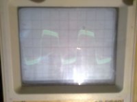
But the only problem I observed is the secondary don't have a clean waveform only when loaded (maybe it's oscillation on positive and negative waves)..
but seems good without load...
So now I know from you that the answer will be.."the Snubbers"..

regards,
demy
 

demykiko

Member
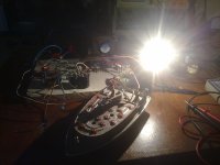
Here some pictures sir..The top view.jpgTop view of the circuit.jpgThe actual 5 min test.jpg

first pic is the top view of the circuit
second pic is the actual 5 min test with load
third pic is the waveform (loaded)
 
Last edited:

demykiko

Member
I think I got an error in saying 680 watts because when I measured the AC input current
it was only 1.85 amperes then If it is multiplied to 234 volts the total input power is 432 watts..
not yet considered the efficiency so the output power will be less than the input..

sir what can you say?
 
Top