blasphemy000
New member
I was in need of a differential scope probe for use in building my SMPSs but at the present time I was unable to afford even the cheapest of differential probes as the cheapest new one I found was $360 dollars and the cheapest used one I found was $200. Now I know that this differential amp I built is not up to par with a professionally manufactured one as far as bandwidth and CMRR goes, but it does function well for what I'm doing as it at least allows me to view the waveform between two non-ground points.
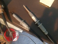
I built this probe using a TL074 quad op-amp which has a slew-rate of 13V/uS. Input attenuation to the amplifier box is X100 so that with a 600V input to a probe gives only 6V to the op-amp's input. I'm achieving this attenuation for each probe by using X10 probes(9M Impedance) coupled with a 100K/560pF input impedance of the amplifier box. I know this isn't ideal, its not completely accurate, and it only gives a total of 9.1MOhm input impedance. I do have 2 X100 probes on order, they should be here soon, and once they get here I will be changing the input stage of my differential amplifier to match the input stage of my scope giving a proper X100 attenuation.
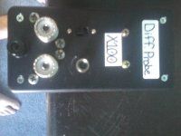
The amplifier box has connections for 2 scope probes. I left the GND of these probe connectors unhooked that way if I accidentally forget and hook up the ground clip of a probe it won't short out and explode. The amp box does have a central earth-ground post located below/between the two probe connectors so that if I am working on a completely floating circuit, ie: battery powered or a completely isolated power supply such as the 16V supply I posted in the DIYSMPS section, I can attach the earth-ground lead to the ground of the floating circuit and make the circuit earth-referenced. The amp will work without this lead attached to a floating circuit, but connecting it does reduce the noise in the circuit. If the circuit I am working on is already earth-referenced, ie: the mains side of a SMPS, then this GND/Earth connection on the differential amp is left unconnected and both of the probes may be connected to points away from GND/Earth.
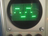
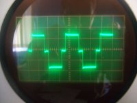
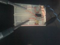
I've posted some pictures, the schematic, and circuit board layout of the current(first) version of this amplifier. In the picture of the scope trace, I have the GND/Earth lead connected to the GND of my 16V floating supply to give it an earth reference, then the each of the two probes are connected to the two outputs of a TL494 running at 50KHz. Now that I am able to measure the difference between both outputs I can easily see the amount of dead-time that is between the outputs, where as before I was only able to measure a single output and was unable to see the deadtime. I have tested this amplifier with the probes connected directly to the mains voltage and I've captured the waveform of a D-S across a MOSFET in an ATX PSU.
The amplifier runs from +9V/-9V power that is supplied by two 9V batteries located inside the box.
View attachment Differential Board.pdfView attachment Differential Sch.pdf
I built this probe using a TL074 quad op-amp which has a slew-rate of 13V/uS. Input attenuation to the amplifier box is X100 so that with a 600V input to a probe gives only 6V to the op-amp's input. I'm achieving this attenuation for each probe by using X10 probes(9M Impedance) coupled with a 100K/560pF input impedance of the amplifier box. I know this isn't ideal, its not completely accurate, and it only gives a total of 9.1MOhm input impedance. I do have 2 X100 probes on order, they should be here soon, and once they get here I will be changing the input stage of my differential amplifier to match the input stage of my scope giving a proper X100 attenuation.
The amplifier box has connections for 2 scope probes. I left the GND of these probe connectors unhooked that way if I accidentally forget and hook up the ground clip of a probe it won't short out and explode. The amp box does have a central earth-ground post located below/between the two probe connectors so that if I am working on a completely floating circuit, ie: battery powered or a completely isolated power supply such as the 16V supply I posted in the DIYSMPS section, I can attach the earth-ground lead to the ground of the floating circuit and make the circuit earth-referenced. The amp will work without this lead attached to a floating circuit, but connecting it does reduce the noise in the circuit. If the circuit I am working on is already earth-referenced, ie: the mains side of a SMPS, then this GND/Earth connection on the differential amp is left unconnected and both of the probes may be connected to points away from GND/Earth.
I've posted some pictures, the schematic, and circuit board layout of the current(first) version of this amplifier. In the picture of the scope trace, I have the GND/Earth lead connected to the GND of my 16V floating supply to give it an earth reference, then the each of the two probes are connected to the two outputs of a TL494 running at 50KHz. Now that I am able to measure the difference between both outputs I can easily see the amount of dead-time that is between the outputs, where as before I was only able to measure a single output and was unable to see the deadtime. I have tested this amplifier with the probes connected directly to the mains voltage and I've captured the waveform of a D-S across a MOSFET in an ATX PSU.
The amplifier runs from +9V/-9V power that is supplied by two 9V batteries located inside the box.


View attachment Differential Board.pdfView attachment Differential Sch.pdf
Last edited:
